The prerequisite to create a stream is the presence of one or more ‘Way’ objects already in the network. Ensure that Ways are already created in the model. As an example, the creation of streams to model a junction is described here. The following two pictures show the BGM (background map image) and Ways created on it:
Junction being modeled

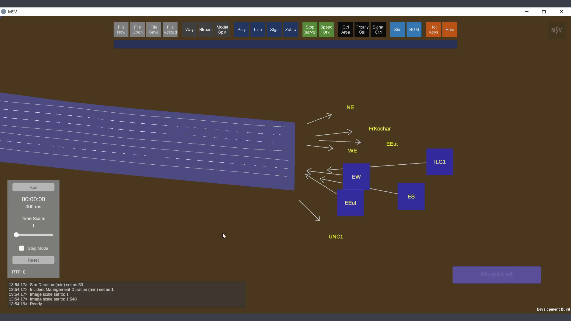
Ways created on which streams will be created (BGM hidden)
To create a stream, click on the Stream button. This will open the Stream Editor. Like other editors in MSV, the Stream Editor contains input fields, Done and Discard buttons, and a close button. The header indicates which stream is currently being edited.
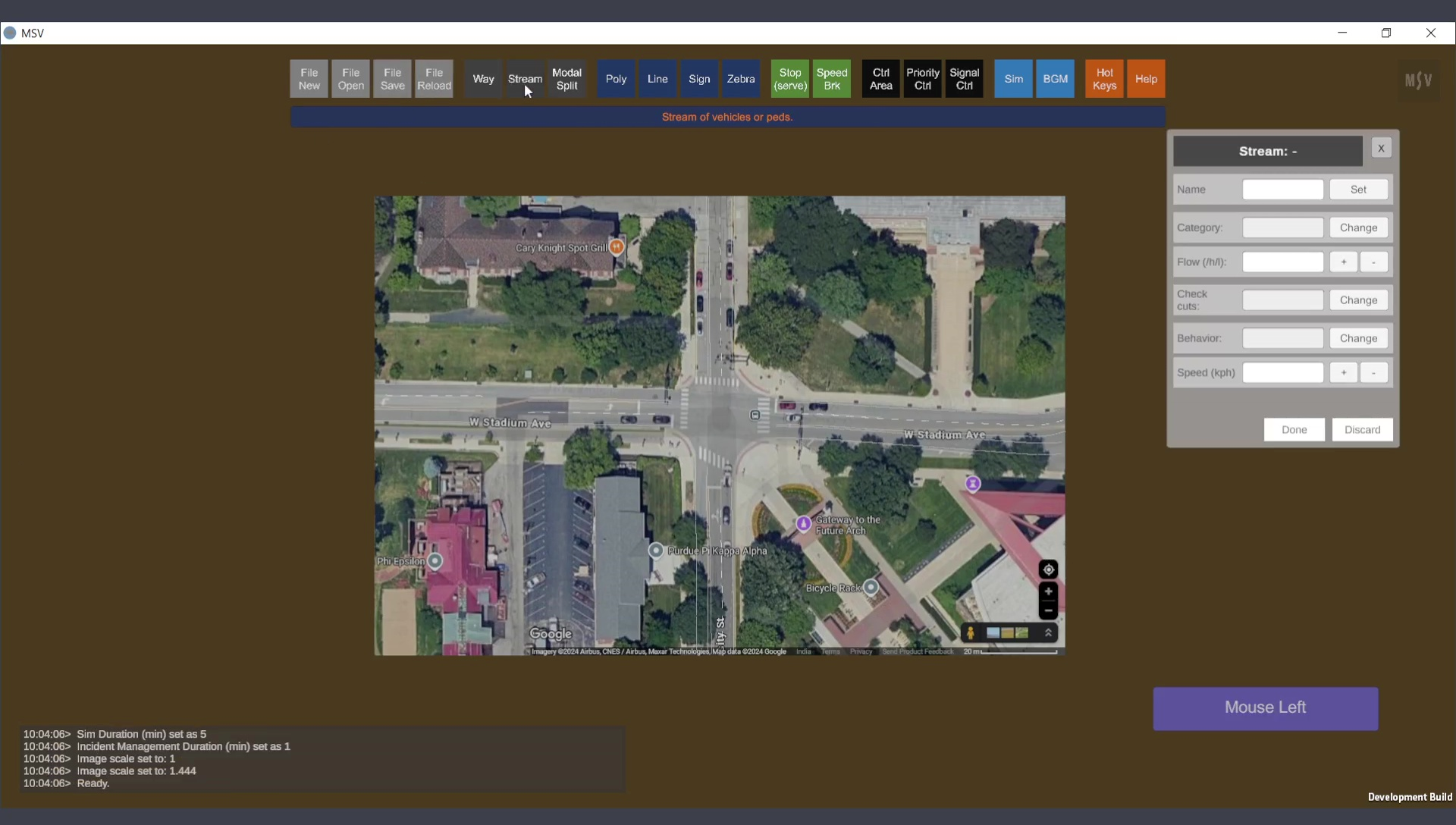
Stream Editor Window
The editor provides six fields for input or selection, as shown below:
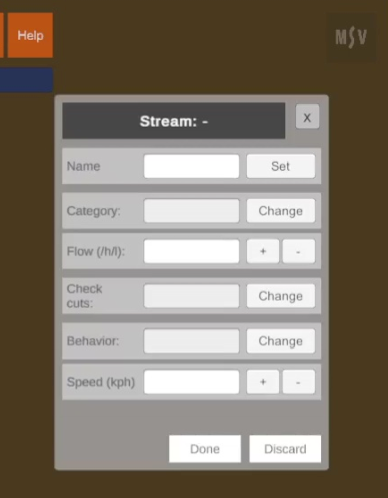
Input fields in the Stream Editor.
Here are the six fields and their purposes:
Once the simulation is run, the program will generate output statistics in text files, detailing the number of vehicles released in each stream. This helps users verify and ensure the accuracy of their data inputs.
We will create a stream that flows in the direction from South to North.
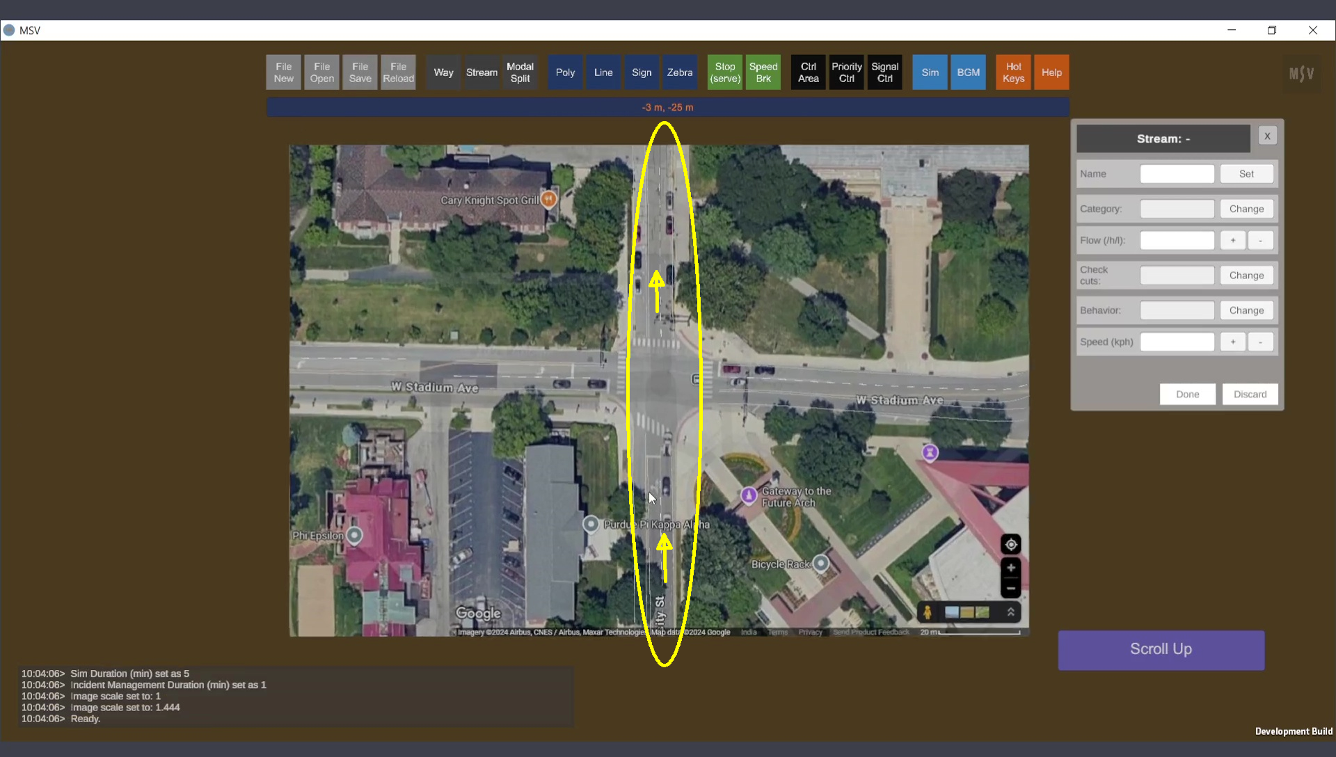
Direction chosen for the first stream to be created.
Note that there are two lanes on both the entry road to the junction and the exit road from the junction. Separate Ways were created for the entry side and the exit side.
Stream creation primarily involves using Ctrl + Left Mouse clicks. Typically, the stream is created along the same direction in which the Way was created. If the stream’s direction is opposite to the Way’s direction, a Shift + Left Mouse click will reverse the stream direction on that Way portion. We will explore these details later.
For brevity, Ctrl + Left Mouse click will be referred to as Ctrl-Click.
A Way can be added to a stream lane by lane. A Ctrl-Click on a lane adds that Way and lane to the stream. Two confirmation lines, blue and brown, will appear. On some monitors, these lines might look reddish. The blue line indicates the left edge of the stream, while the brown line marks the right edge. Repeating a Ctrl-Click on an already selected lane will deselect it.
To add another lane, perform a Ctrl-Click on that lane. The blue and brown lines will adjust to represent the new stream width.
When creating a stream from South to North, if a Ctrl-Click shows the brown line on the left and the blue line on the right (from your perspective), the stream is actually pointing from North to South. This happens if the Way was originally created from North to South. A Shift-Click will instantly correct the stream's direction. With a few minutes of practice using Ctrl-Clicks and Shift-Clicks on existing models, it becomes intuitive.
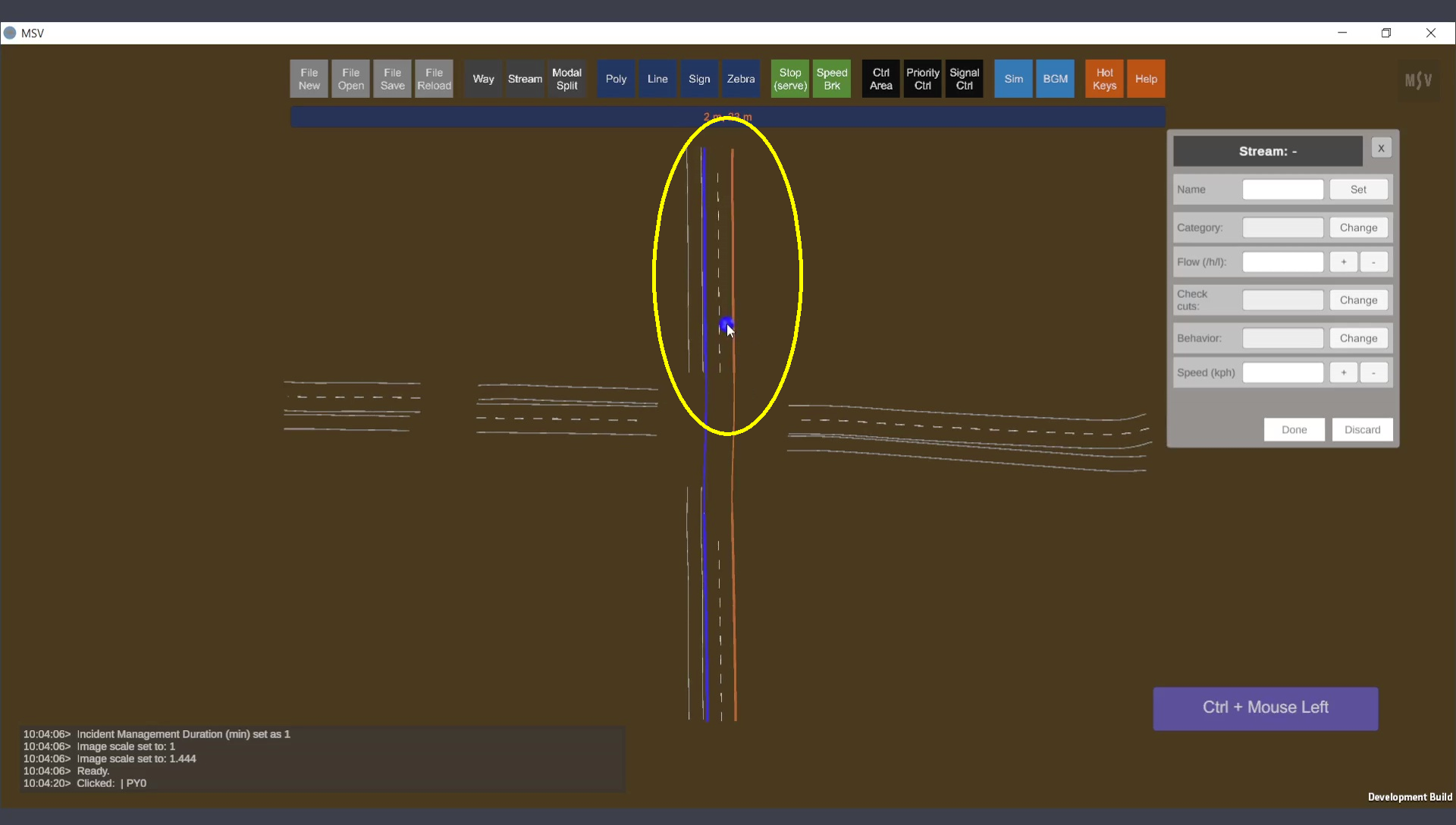
In the screenshot below, the stream creation begins with a Ctrl-Click on a lane of the approach leg’s Way. This junction is located in Purdue, United States, where traffic flows on the right. MSV is side-tolerant, allowing users to choose any Way where flow occurs. For instance, in India, where traffic flows on the left, the solo lane on the left side of the road would have been selected instead of the two lanes on the right side.
Note that no data will appear in the editor until the Done button is pressed. The Done button is clicked after all necessary lanes and Ways are selected via Ctrl-Clicks, signifying the stream is complete.

One lane on a Way is chosen as the first part of the stream.
We then include both lanes in the Way. Another Ctrl-Click is performed on the second (outer) lane. The brown line shifts further to the right, indicating that the stream now covers both lanes.

Both lanes are selected for the stream in the first Way.
Continuing with the stream creation, Ctrl-Clicks are performed on the next Way object in sequence, located on the opposite side of the junction. The blue and brown lines immediately extend to the new section, indicating the stream's path. For the first time, we observe a connection between the Ways. This connection does not involve a physical drawing on the road space but exists within the stream's data, stored in the program's memory. Such connections are automatically saved in the input files when the model is saved.

The stream extends to the next Way object.
Next, we include the right lane in this section. Performing a Ctrl-Click on the right lane now forms a complete stream comprising two Ways, with two lanes in each Way.
Second lane in the second Way is added to the stream.
Both lanes in the next Way are included:
Second lane in the second Way chosen
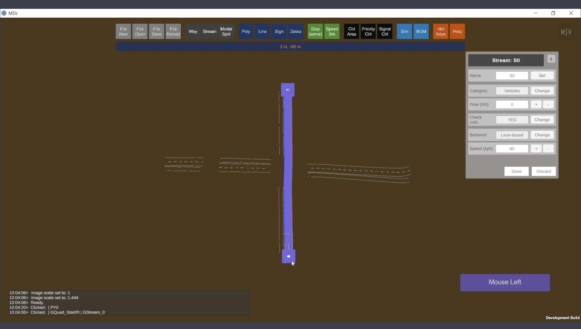
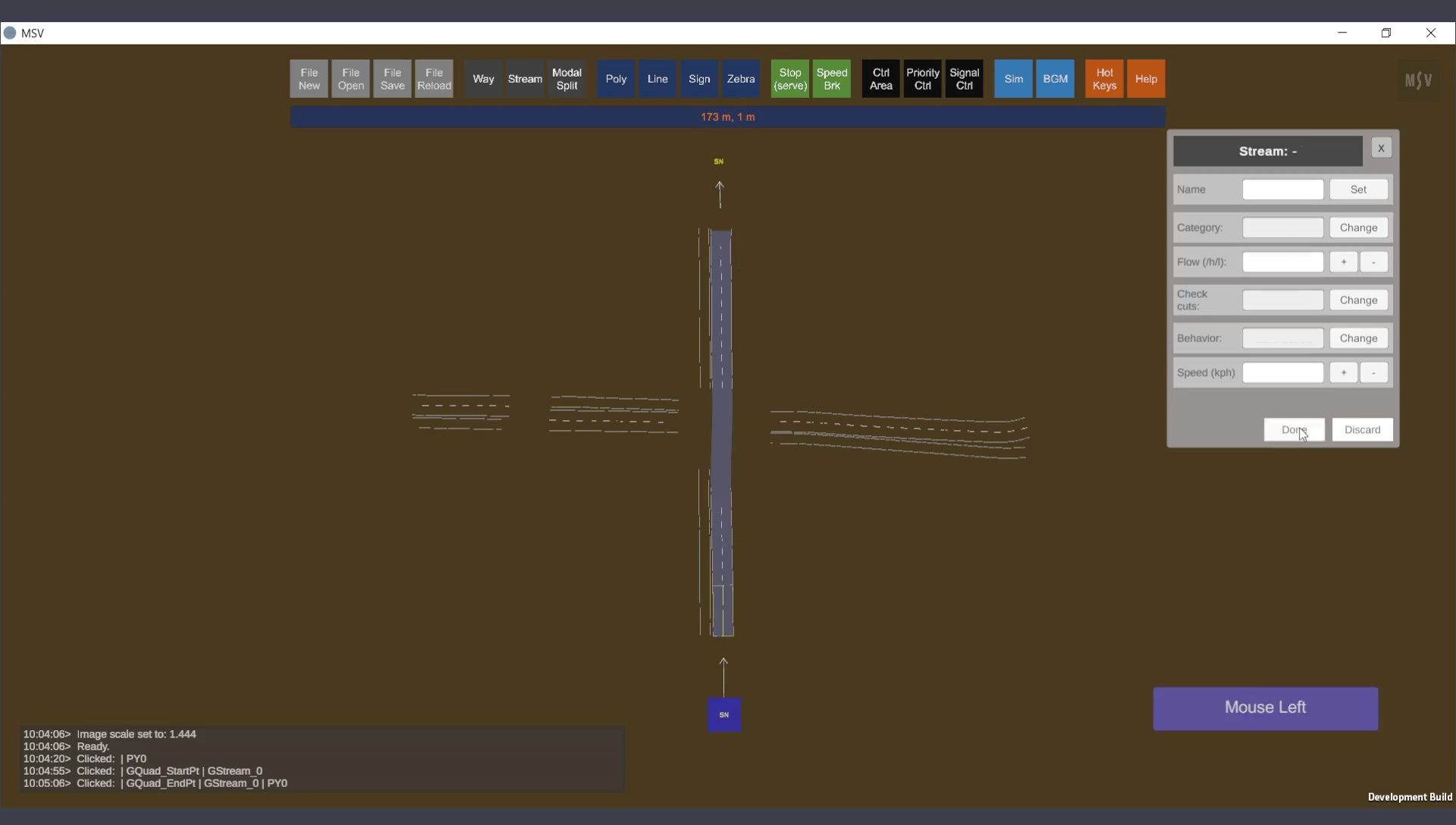
After selecting the lanes on the Way objects, press the Done button. This action removes the blue and brown lines, displaying the full form of the stream as a gray strip. Additionally, two quads will appear at the ends of the stream (small square planes where the stream name is shown). The quad at the starting end is blue, while the quad at the other end is temporarily hidden. However, names appear at both ends. These quads act as handles for the stream, allowing users to easily identify the start and end points.

Pressing the Done button completes the creation of a basic stream.
To make changes to a stream, first select it with a plain click. The stream will then be highlighted, and its default data will be displayed in the editor. If a stream is already selected and being edited, another stream cannot be selected. To switch to editing a different stream, either press Done to save the changes, or Discard to ignore them for the currently selected stream. Only then can a new stream be selected for editing.
The following properties can be configured for the selected stream:
Before entering data into the input fields of the editor, the starting and ending side quads can be repositioned to make the visualization neat and readable. To reposition a quad, select it with a normal mouse click. A white blob will appear on the selected quad, as shown below:
Selecting a stream and choosing a quad at one end.
The quad can then be moved using Shift+Click (or Shift+Arrow keys). Adjust its position just enough to make the arrow pointer clearly visible, indicating the direction of flow. See the example below:
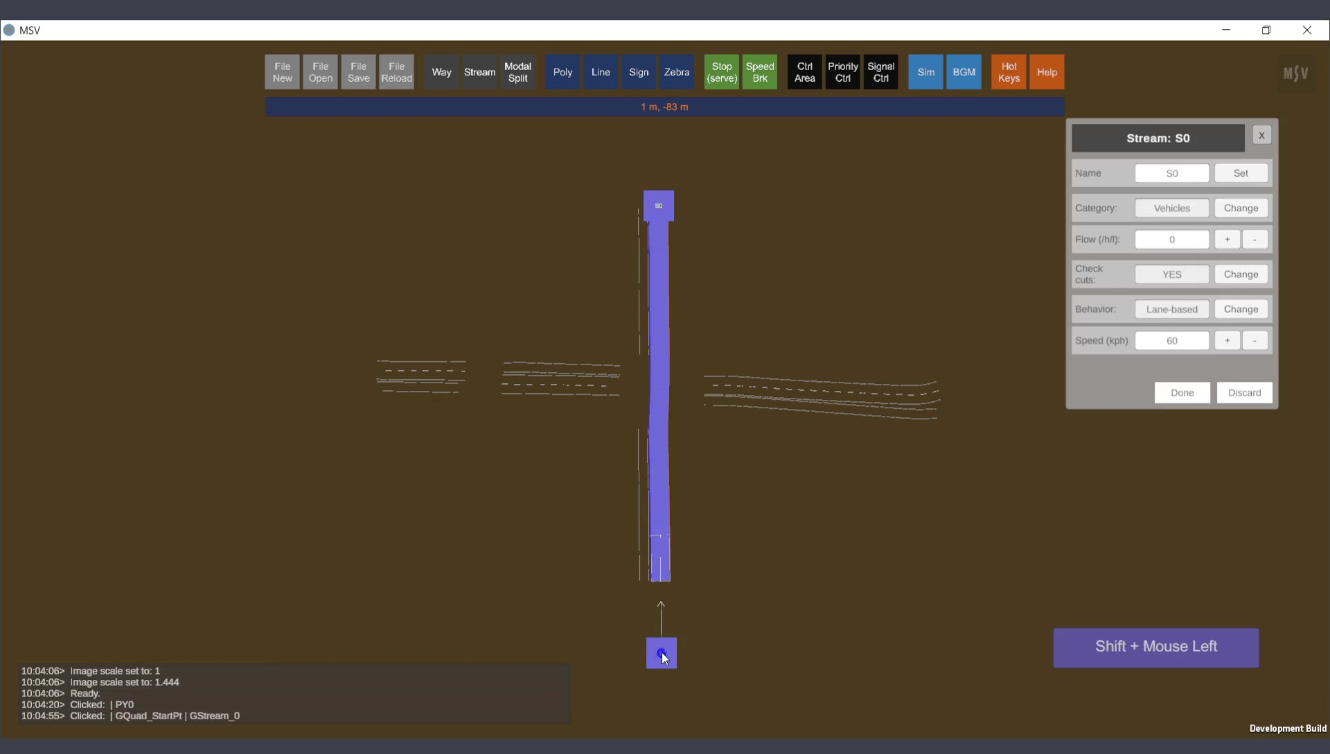
Positioning the quad on one end for better visibility.
Similarly, select the quad on the other end and reposition it to a desired location nearby using Shift+Click.
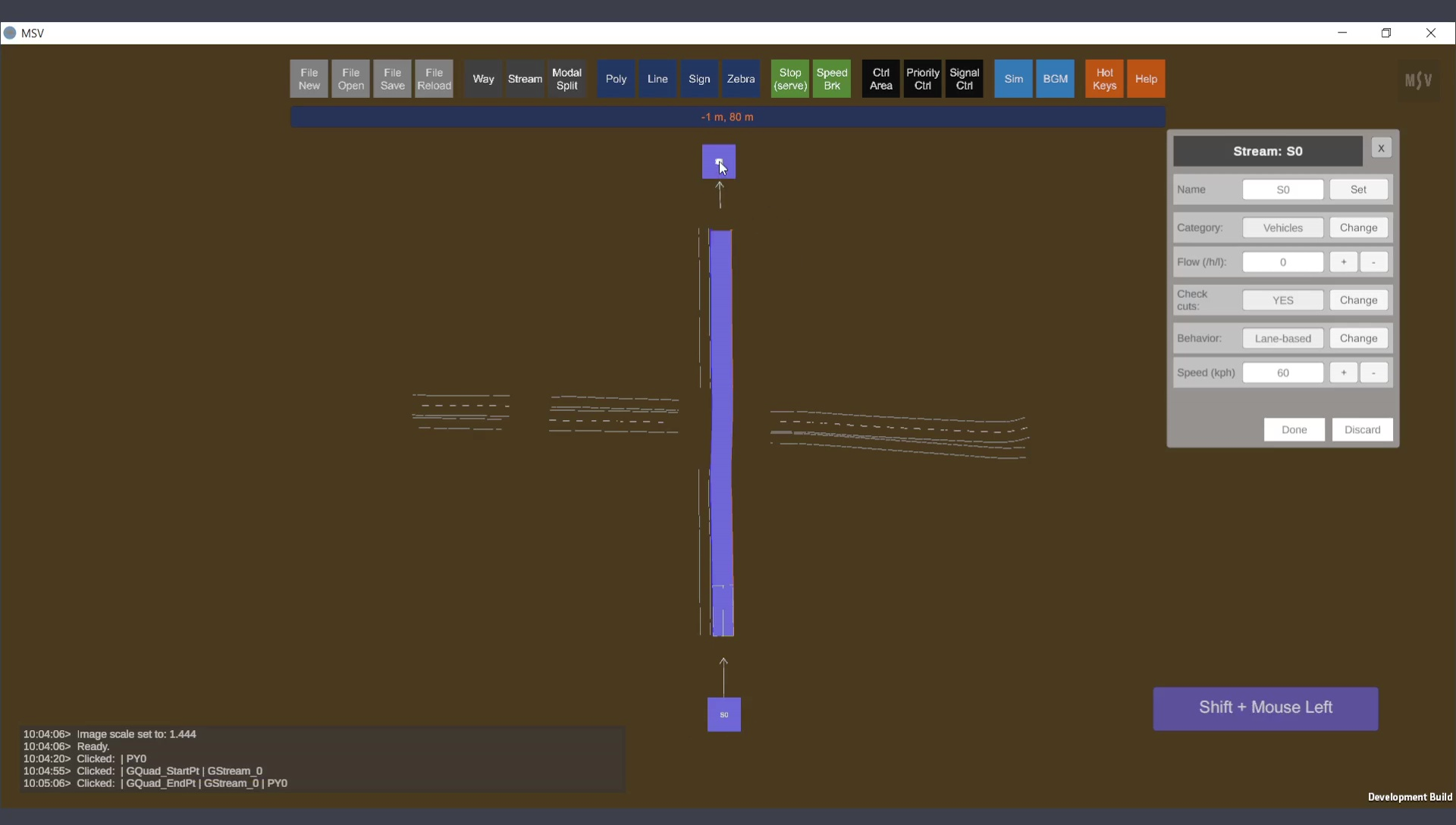
Repositioning the quad on the other end.
Repositioning the quads is solely for visual convenience and does not affect the stream or its functionality.
To name a stream, enter the desired name in the text field labeled ‘Name’ and press the ‘Set’ button. The name can be changed at any time. In this example, the stream is named ‘SN’ to indicate the direction of flow, South to North.

Assigning a name to the newly created stream.
Naming streams is particularly helpful when the number of streams in a model increases. For instance, consider the snapshot below, which is part of a model in Chennai (India). In this model, traffic flows on the left. The left side of the road has two lanes, and the right side has three lanes (when viewed from the east end). Four streams originate at this location (indicated by blue quads), and five streams terminate there. Note that streams may share the same lanes within the two-lane and three-lane Way portions of the road. Quads and stream names make it easier to identify the origins and endpoints of streams.
Stream start and end quads with names for better identification.
Typically, stream strips are not turned on to avoid cluttering the scene. Instead, Way shapes and polygon base shapes are sufficient for viewing the model. However, when editing streams, turning them on can help identify which stream to select and edit.
Below are two images: one with streams switched On and another with them switched Off. When streams share the same Ways, graphical cards in the computer may display them simultaneously, causing some fuzziness where they overlap. Streams can be toggled On and Off by simply pressing the letter ‘S’. Information about hotkeys, such as this, is displayed in the Reporter when the Hot Keys button on the top row is pressed, or by pressing ‘H’. For example, polygons can be toggled On and Off with the letter ‘P’, and similar hotkeys exist for other objects.
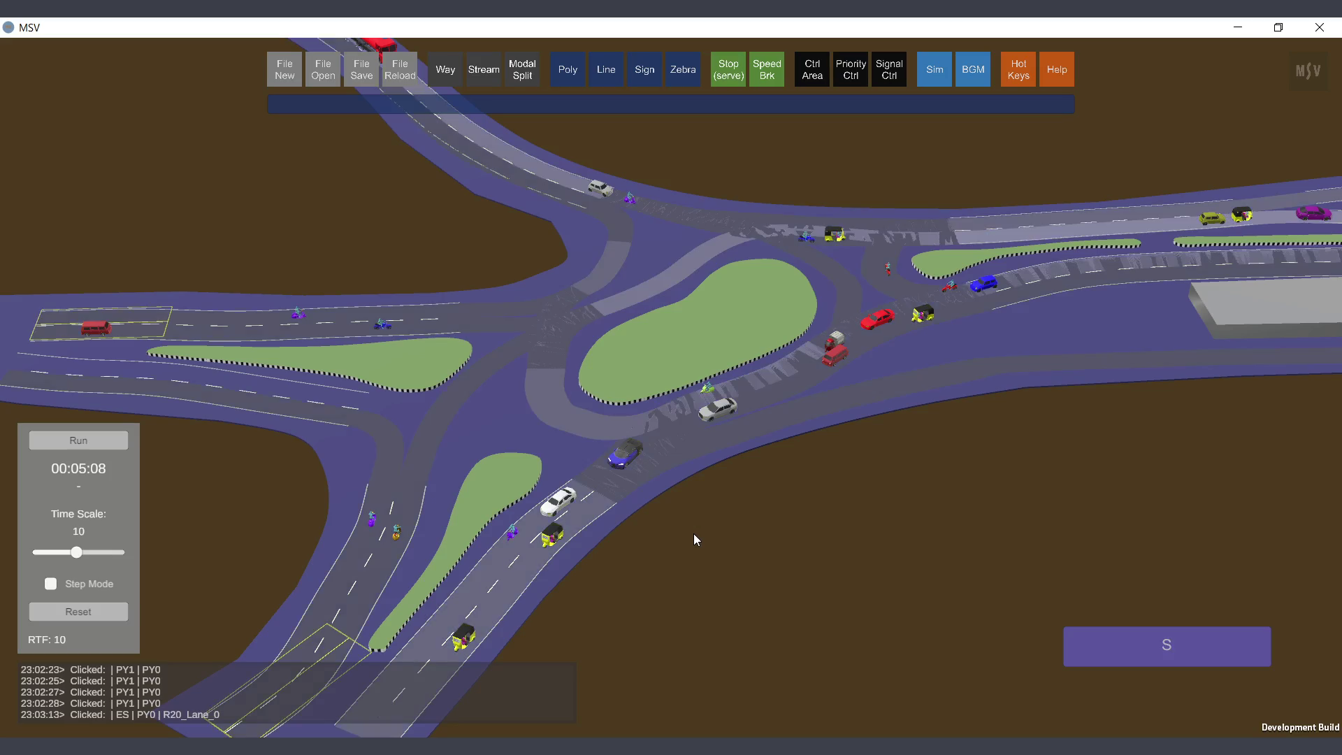
Overlapping streams might appear fuzzy when switched On, as shown here.
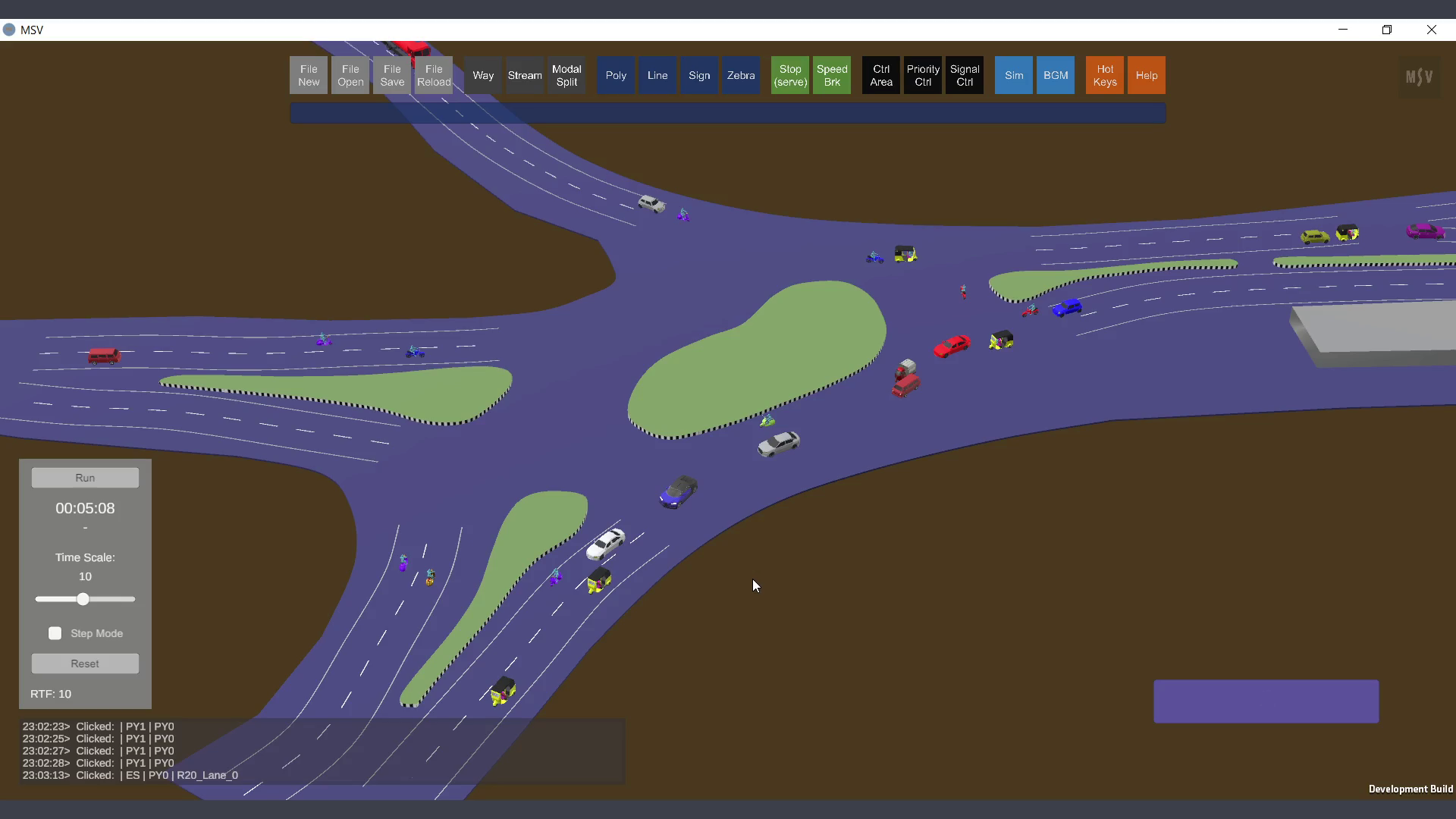
Switching streams Off and turning on Ways and Polygons creates a cleaner simulation view.
When streams are switched On, two long rectangles appear at the start of the stream on the stream strip itself. These are the release spots where vehicles begin their journey on that stream during the simulation.
The flow value represents the number of vehicles expected to be released into this stream per hour for each lane of the first Way in the stream.
In the example below, a value of 180 is entered. After typing the value, remember to press the Enter key to confirm it.
The plus and minus keys can be used to increment or decrement the flow value by 50, respectively. Additionally, system-level demand can be adjusted without altering individual stream flow values by using the demand factor in the Simulation Settings, which is described in another section of this manual.
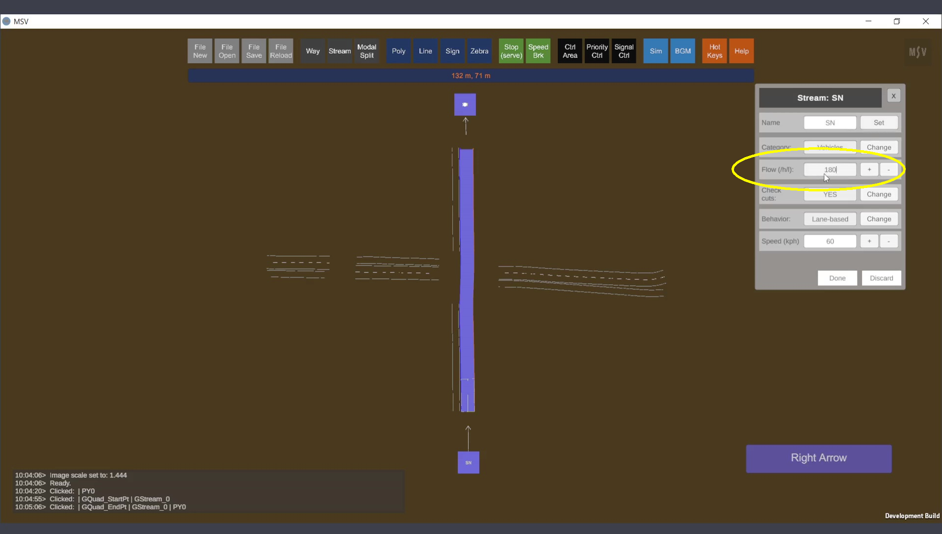
Flow value entered in the editor.
For now, leave the other data fields at their default settings. Once the flow value is set, press the Done button to complete the current stream configuration and proceed with creating additional streams.
Pressing the Done button after setting the flow value.
Create multiple streams originating from the same Way by selecting the appropriate lanes. For example, South-West (SW) and South-East (SE) streams share lanes with the SN stream:
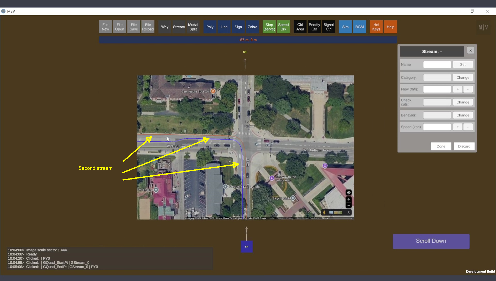
Second stream’s path
Third stream (SE)
All three streams are displayed in the screenshot below. The Modal Split Editor was opened by clicking on the Modal Split button.
The Modal Split Editor allows you to specify the percentages for different vehicle types, such as cars, vans, and others, within the flow value assigned to each stream. This is known as modal split, where various modes of transport divide the overall flow value.
Field observations can provide data for modal split. For newly proposed junctions, different combinations can be tested to evaluate the junction's capacity performance.
When entering data, watch the Reporter to ensure the total sums up to 100%. The Done button will remain inactive until this condition is met. Remember to press the Enter key after typing each value. Alternatively, use the Plus/Minus buttons for quick adjustments.
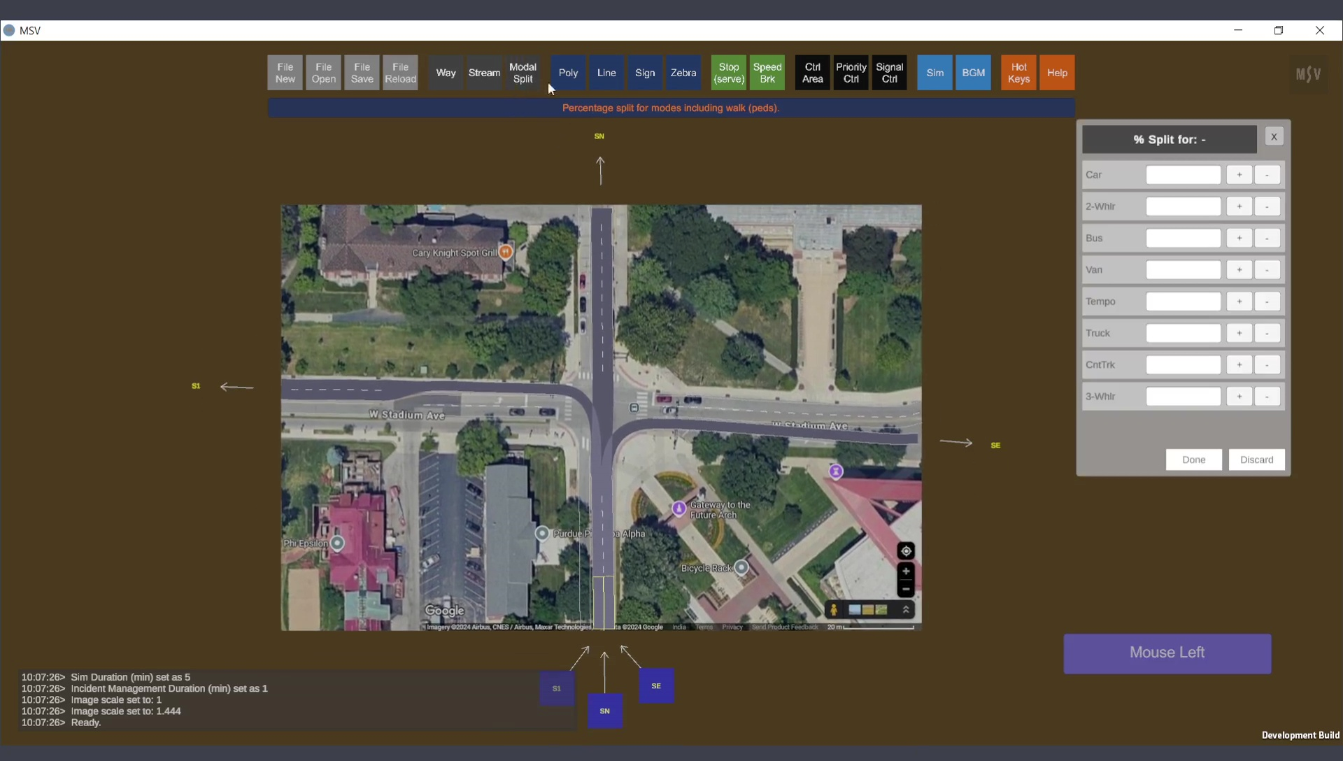
Modal Split Editor
Hovering the mouse over streams will highlight the stream directly beneath the cursor. Click on the desired stream to select it. The modal split values for the selected stream will be displayed in the editor.
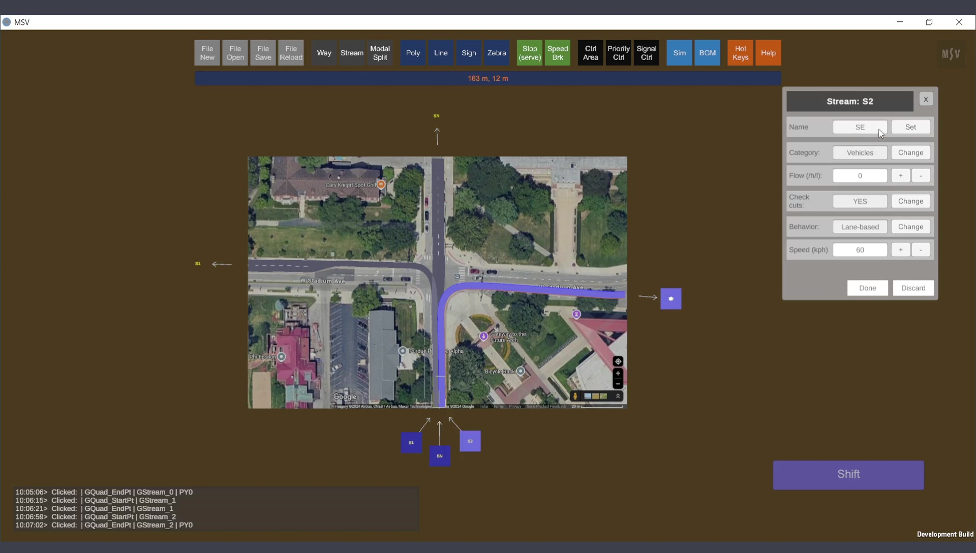
In the example below, the SN stream is selected, and test values are entered. There are eight major vehicle groups to configure percentages for. Each category encompasses different vehicle models (e.g., cars may include sedans, mini cars, etc., divided equally within their share). If there is a demand for specific vehicle types not currently available, they can be added in future software updates.
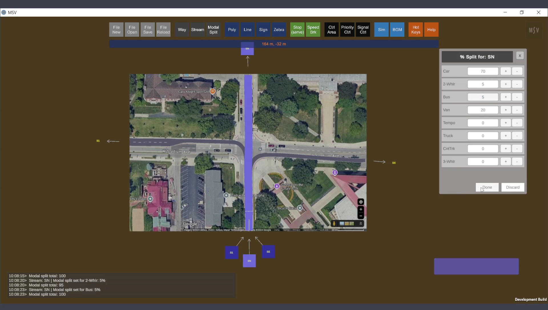
Modal split values entered in the editor for the SN stream.
Models often contain numerous streams. For instance, the junction being modeled may have at least 12 streams (three for each entry leg of the junction). Including U-turns raises this number to 16. Entering modal split values individually for each stream can be time-consuming. However, there is an easy option: specify modal split values for one stream and copy them to others using a simple Alt-Click operation.
The image below demonstrates this process. The SE stream is selected, and its modal split values were copied from the SN stream. To copy, simply Alt-Click the source stream (from which you want to copy data). A confirmation message will appear in the Reporter. You can tweak or modify the copied data as needed for the selected stream.
After setting the modal split values, save and reload the model to finalize the changes.
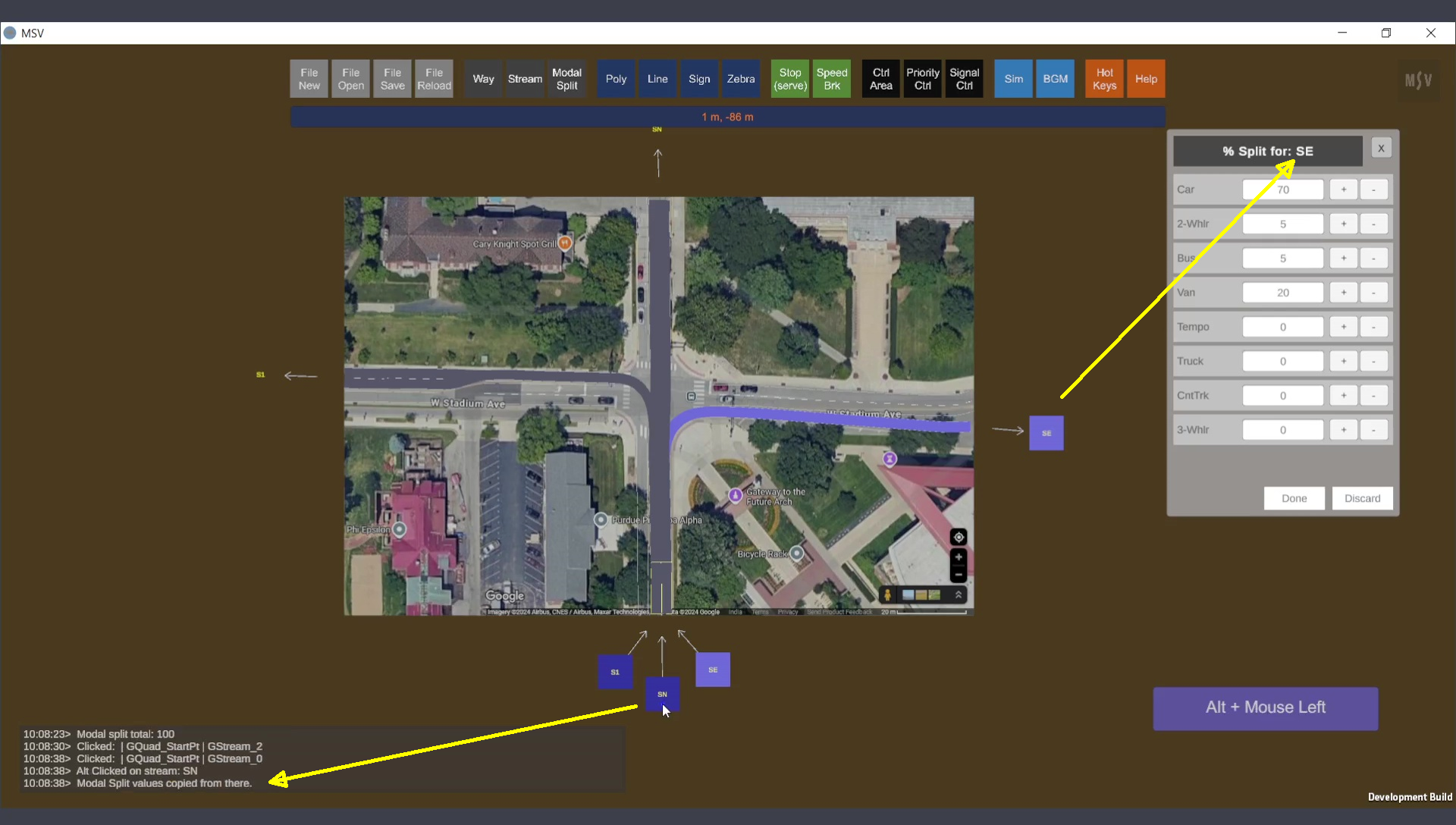
Copying modal split values from one stream to another.
The simulation control panel, featuring the Run and Pause buttons, can be used to start the simulation. Click on the Run button to initiate the simulation. Vehicles will begin moving along the stream.
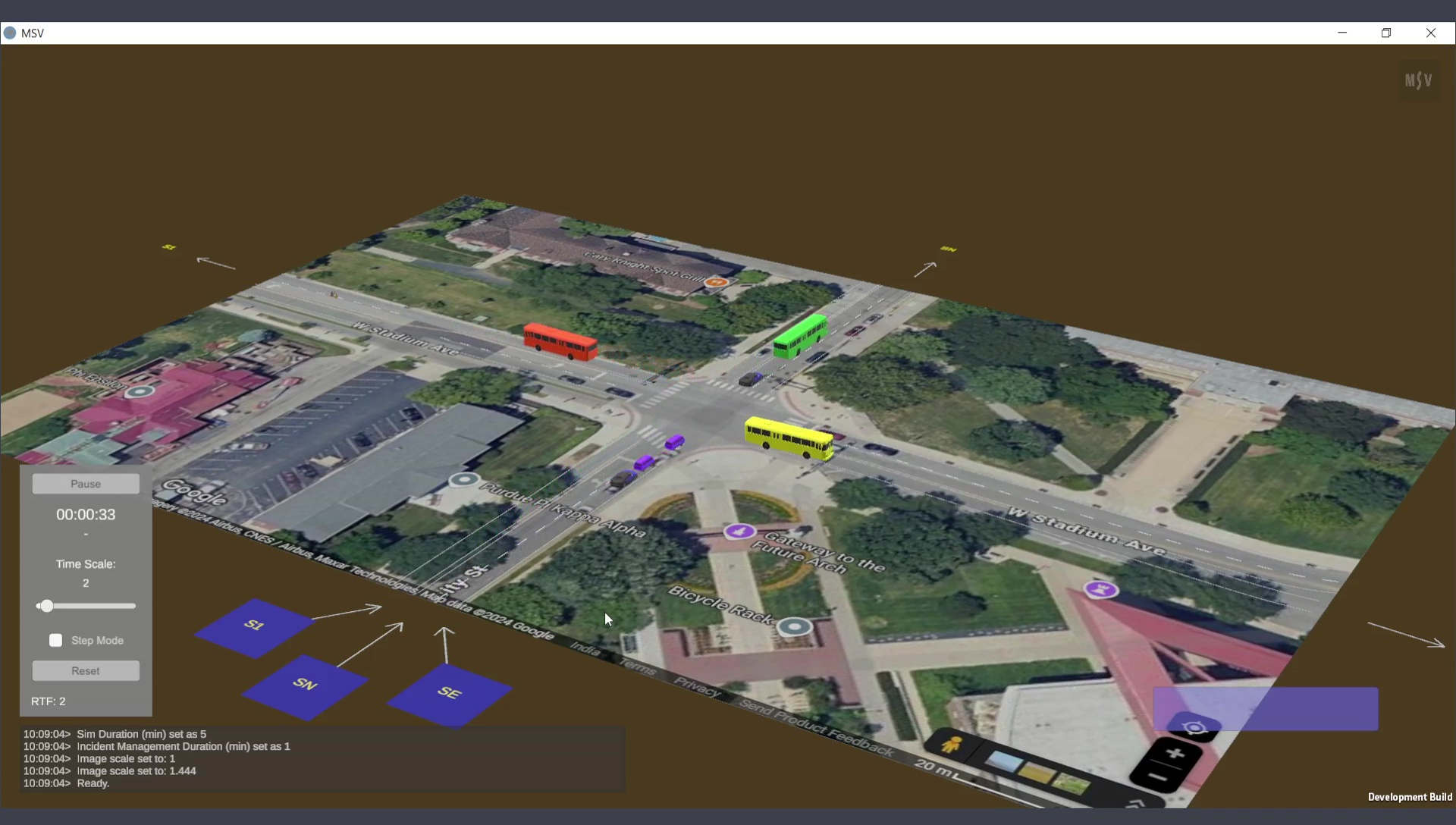
Vehicles moving for the first time in the newly created model.
If a vehicle cannot be released on time due to the sharing of lanes or Way, it will be temporarily held in the computer's memory. The vehicle will be released as soon as the previous vehicle occupying the space has cleared the release spot.
With this, the process of creating simple streams and testing their operation in a simulation is complete. If errors or mistakes occur, the Reporter will display relevant messages. If the simulation runs smoothly, it indicates that the streams are functioning correctly.
Simulation can be run from real-time to 20x speed. The simulation control panel has a slider for this setting. Vehicles move at the same speed irrespective of the simulation speed. A 20x speed means 20 minutes of simulation can be completed in 1 minute of real-world time. Depending on the computer's processor and memory capabilities, and the current number of vehicles in the scene, the simulation speed may decrease. To optimize performance during long simulations, object visibility can be switched off. This is discussed in detail in another section of the manual, ‘Simulation Speed’.
To configure other key simulation settings, open the Simulation Settings Editor by clicking on the ‘Sim’ button. Set whether traffic flows on the left or right side of the road (refer to the image below). This setting is crucial when stream widths change from one Way to another, requiring vehicles to change lanes, particularly when stream widths narrow. Additionally, overtaking behaviors differ between left-side and right-side traffic operations, and this setting ensures the simulation accounts for those differences.
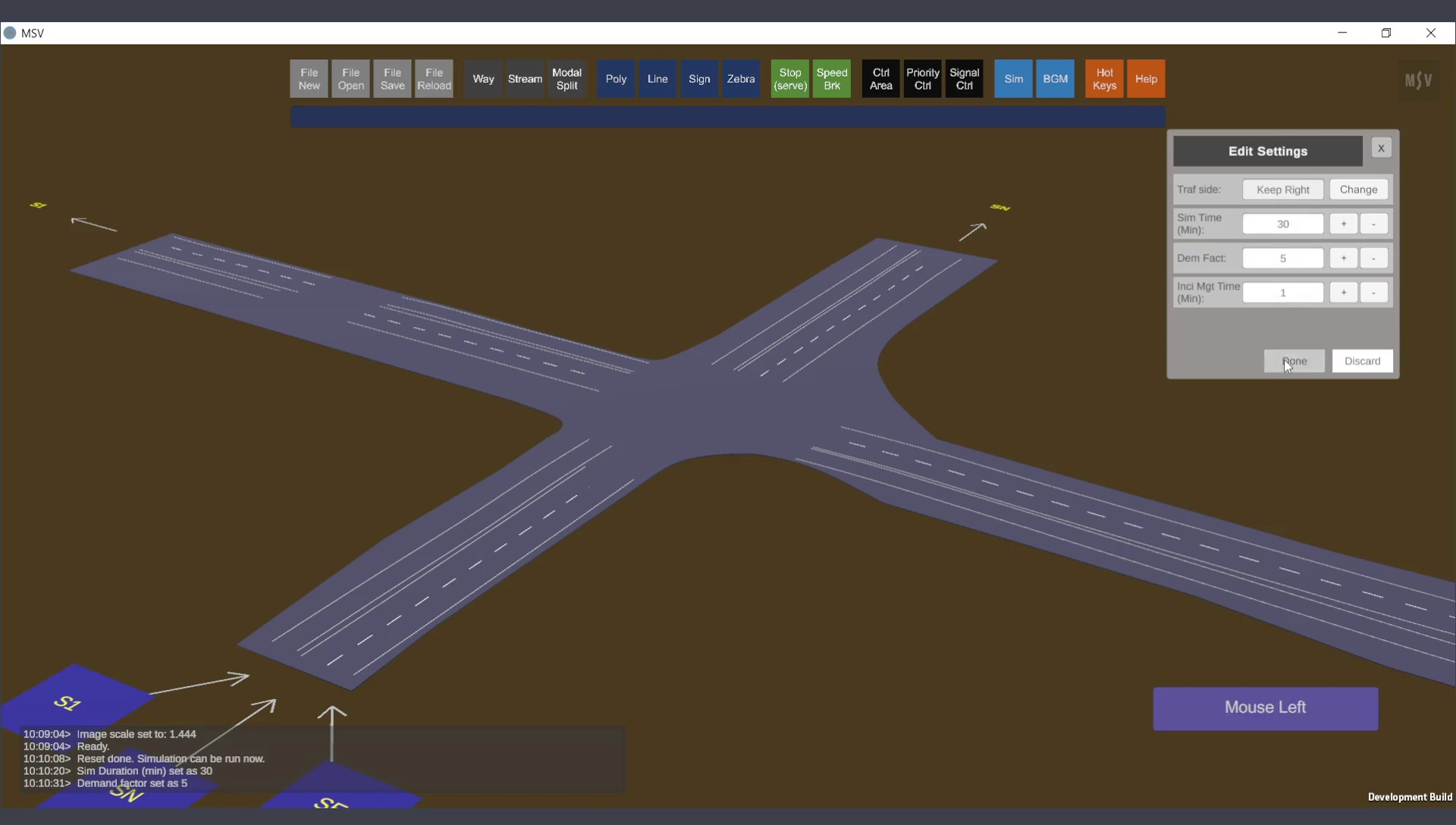
Simulation Settings: Streams are Off, while Poly and Ways are On (visibility only; functions will be active for all objects during the entire simulation).
The simulation duration can be set as needed. For example, a duration of 30 minutes can be specified. The maximum allowable duration is 1440 minutes (one whole day). To adjust the overall flow values in all streams simultaneously, use the multiplying factor called “demand factor” in the Simulation Settings Editor. In this instance, it is set to 5 times. The incident management time field can remain at its default value of 1 unless adjustments are necessary.
After configuring the simulation settings, the simulation can be run using any preferred view combination. For instance, with streams switched Off for visibility, Ways and Polygon base layers can be switched On to provide a cleaner view:
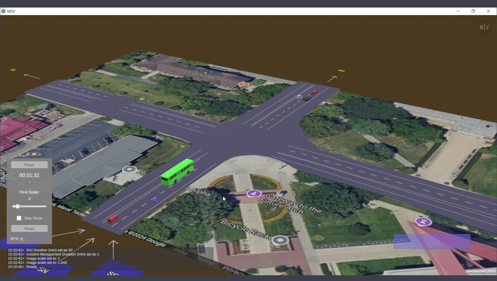
Simulation view: Streams are Off for visibility, while Ways and Polygon base are On, along with the BGM image.
It is important to note that if a Way is deleted after streams have been created, the associated streams will also be deleted automatically. However, if the type or width of the underlying Way is modified, the streams will update themselves to reflect the new width. If the number of lanes is changed, users should revisit the streams to ensure they are correctly aligned with the intended lanes. If necessary, use Ctrl-Click to edit lane assignments. Advanced topics in this manual will cover such scenarios in greater detail. For simpler junctions, it may be easier to re-create the streams after making extensive changes to the Ways.
When streams intersect, this is where control strategies such as priority control and signal control are modeled. Detailed procedures for these strategies are explained in other sections of the manual.