In MSV, a signal controller regulates the movement of streams passing through a control area linked to it. Multiple control areas can also be linked to a single signal controller.
A signal controller is essentially a timer that runs a sequence of phases, each with three sub-durations: green, yellow, and red. The cycle loops continuously. If a control area is linked to a signal controller, streams passing through it are automatically controlled. Users can specify which streams are allowed to move during each phase using the Signal Editor. For instance, at a junction where streams A and B cross, a control area C covering the junction can be linked to a signal X. During phase 1, stream A can be set to green while stream B stops, and vice versa during phase 2. This setup prevents collisions.
Vehicles stop or slow down based on the signal phase. Streams with a red signal stop at the perimeter of the control area (akin to a stop line). Configuring the control area properly ensures realistic signal operations.
In MSV, a signal is represented by a quad shape with its name displayed on it. Colored lines appear at the stop-lines of a junction to indicate which direction has green or red. Unlike physical signals, no posts or bulbs are used for representation. The lines showing the phases can be hidden or shown by toggling the visibility option using the letter ‘X’ for signals, if needed.
Screenshots showcasing the signal operation at a typical four-way junction in India are presented first. The operation has five phases. This is followed by a detailed description of how to create a signal for a T-junction from scratch.
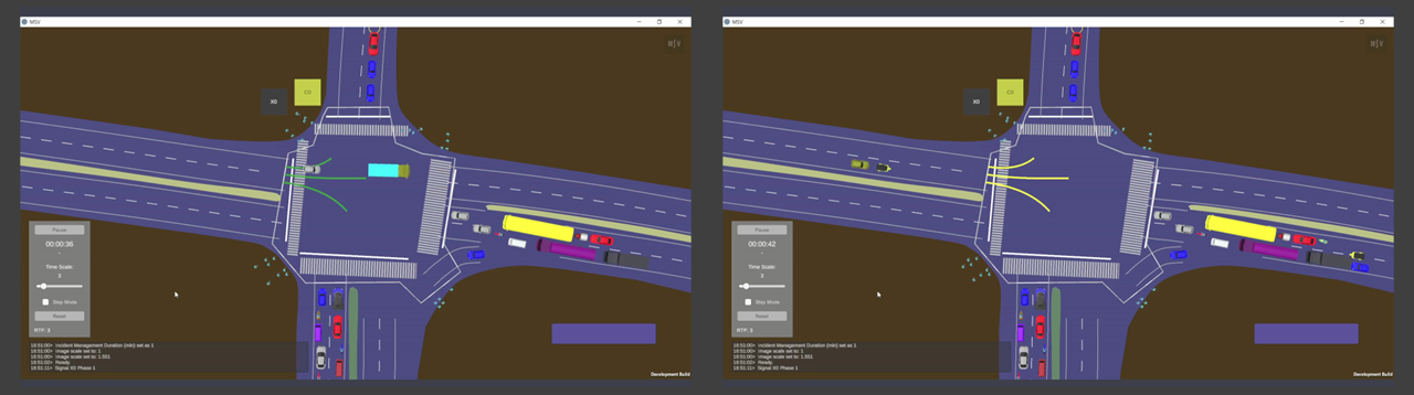
Two screenshots showing green and yellow times in phase 1.
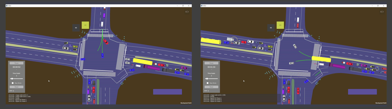
Screenshots for phase-2 and phase-3 operations.
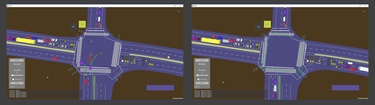
Phase-4 for vehicles and phase-5 exclusively for pedestrians.
The Signal Editor interface is shown below:
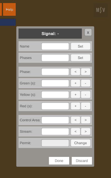
Signal Editor.
The editor consists of three sections:
The Free option is useful for streams like free-left or free-right turns that do not require control.
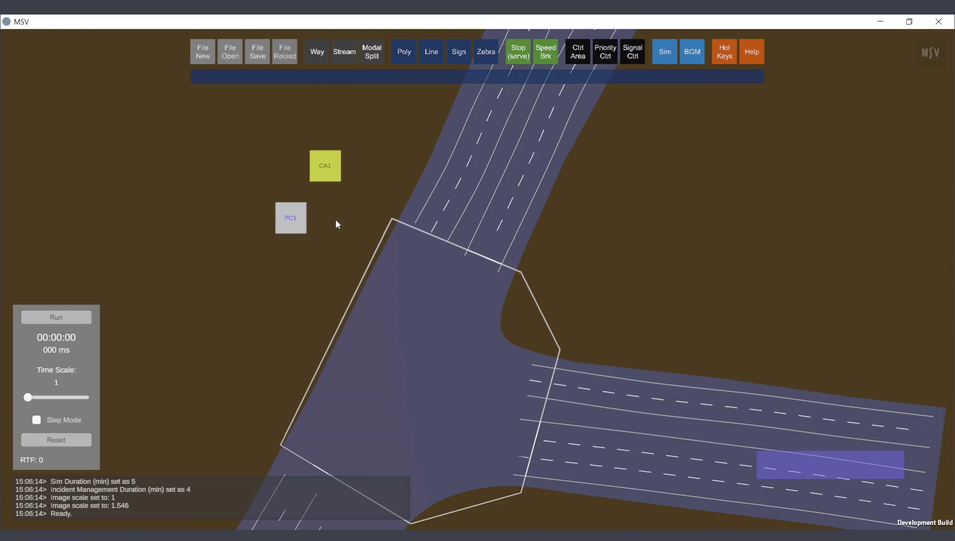
Consider the T-junction shown below, which already has a control area and a priority controller. There are two quads: one in yellow, which serves as the handle for the control area and the line that goes around the junction, and one in cyan, which represents the quad for priority control.
Control area for which a signal controller will be linked.
In a nutshell, here is the procedure:
The step-by-step procedure is detailed below.
To create a signal controller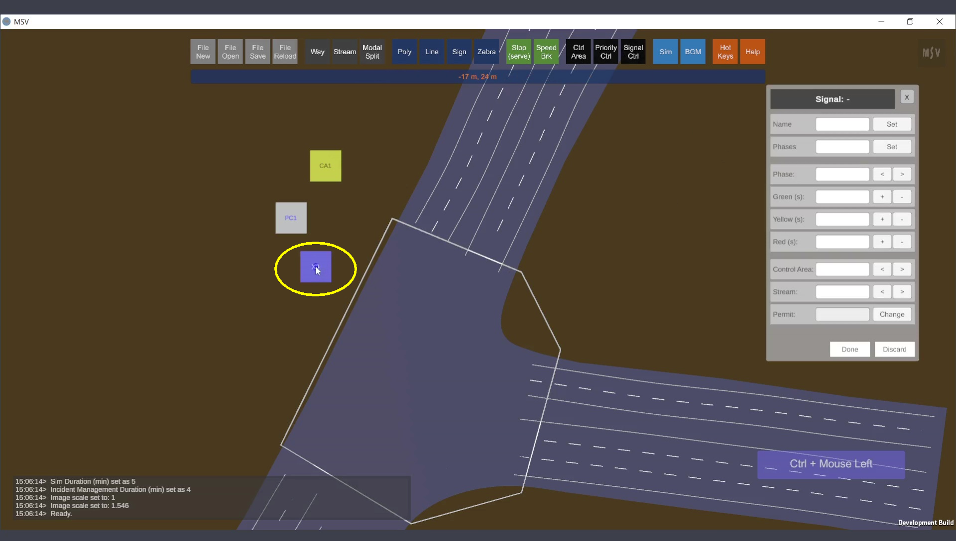
Signal controller creation started.
Press Done and select the signal quad to edit its data. Initially, the editor displays default values:

Default input fields when a signal is selected for editing.
Set the following values for the T-junction (for demonstration purpose):
Press the Set button for the Name and Phases fields, and press Enter for the durations. At this stage, the signal runs in the simulation, but vehicles will not respond to it until the control area is linked:
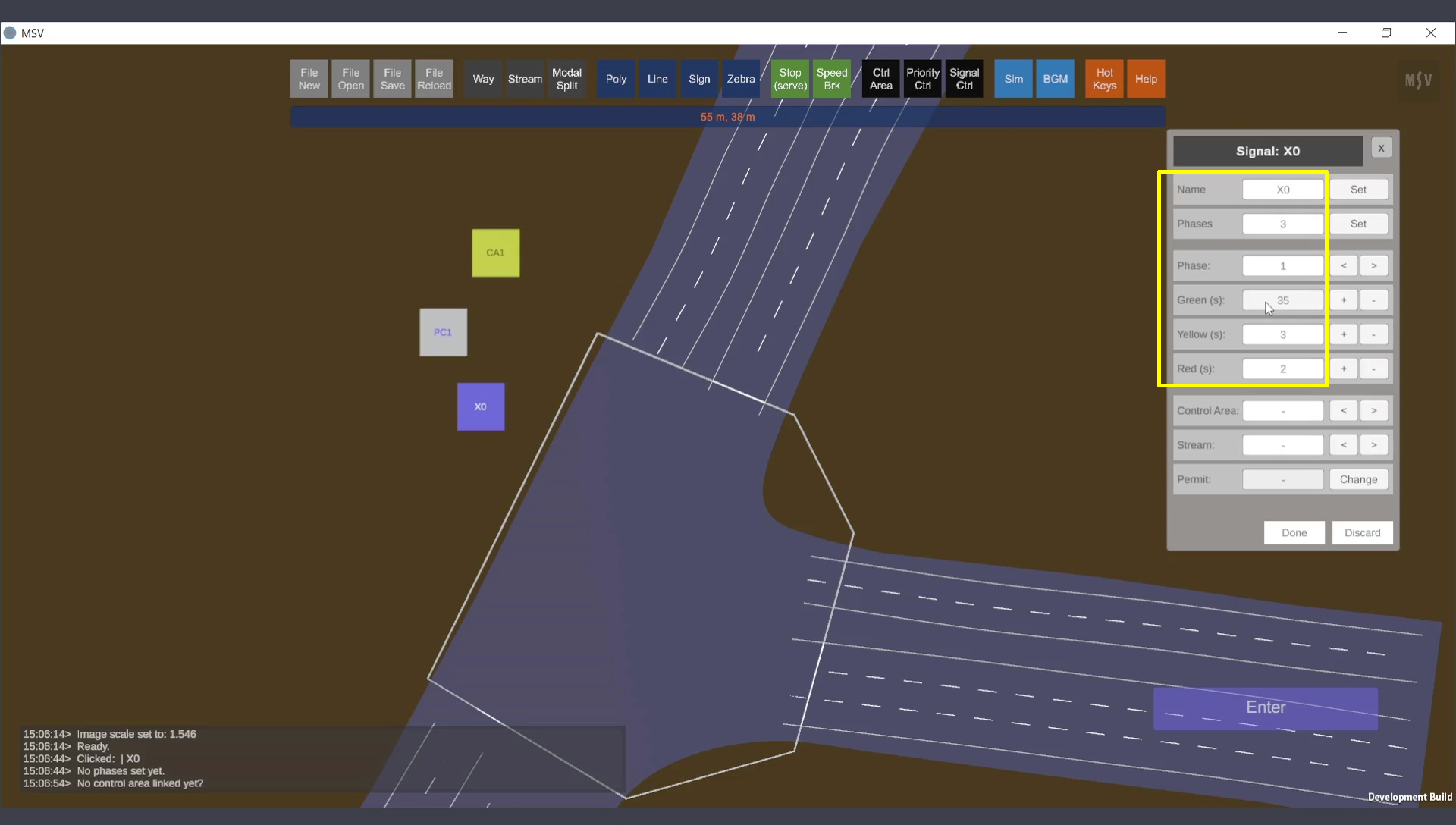
Three phases set with durations for the controller.
To link a control area to the signal:
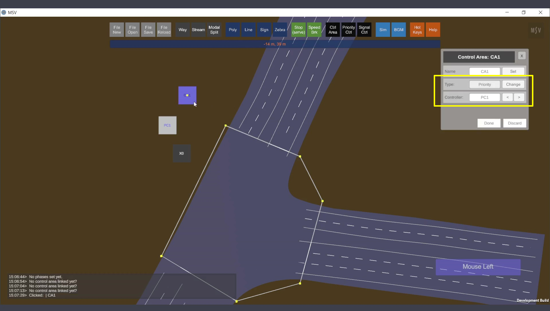
Control area chosen for linking to signal control.

Type changed to signal control, and signal controller linked.
Press Done. Save and Reload. Reopen the Signal Editor and select the signal controller X0. The editor will now display the linked control area and streams:
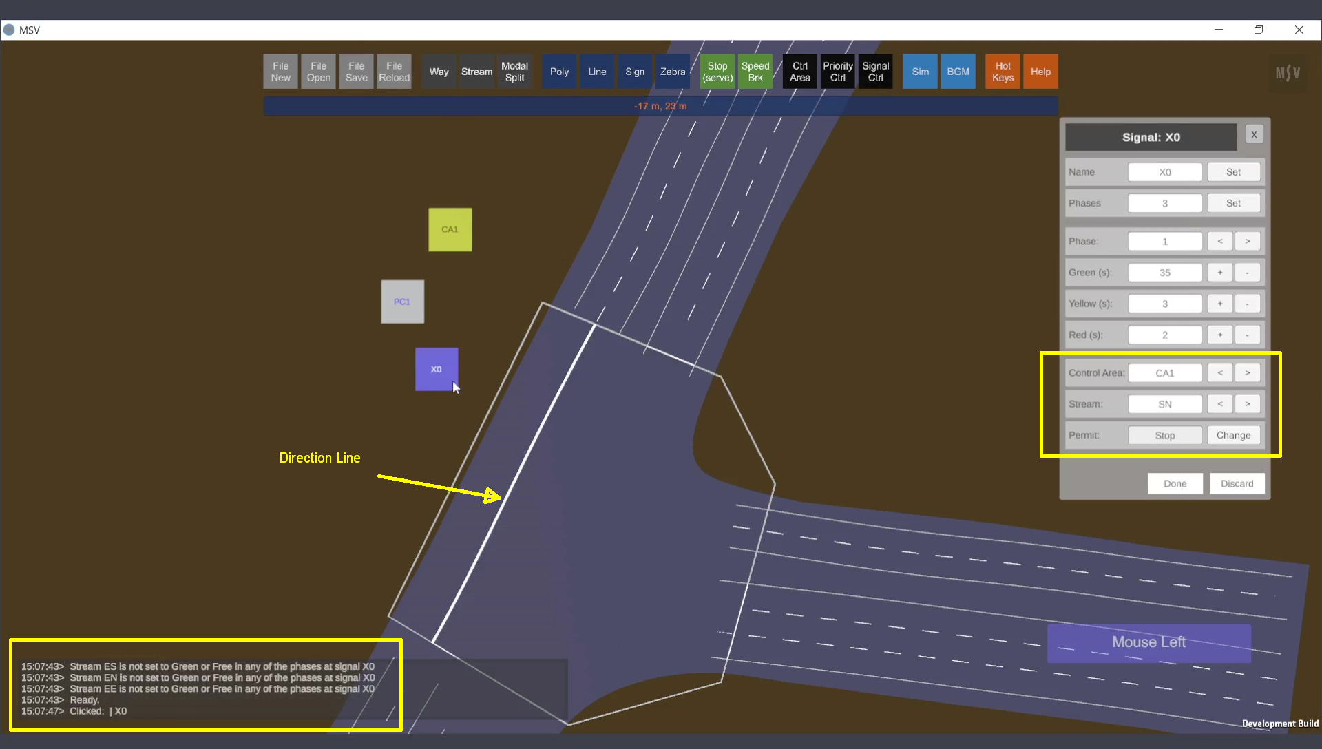
Streams displayed for the control area linked to the signal.
There are three important points to note in the picture shown above:
For vehicles coming from the south, phase-1 is set to give green. This allows streams originating from the south to receive a ‘Go’ permit. Similarly, in phase-2, streams originating from the north are assigned green, and in phase-3, streams originating from the east are set to green. The following picture illustrates the configuration for phase-1.
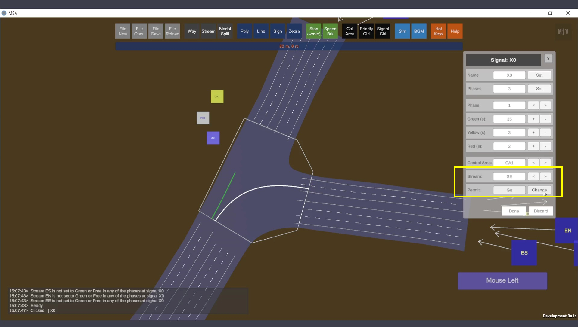
Phase 1: Streams starting from the south set to Go.
To better visualize the streams, you can hide the polygon base by pressing the letter ‘P’, hide the way objects by pressing ‘W’, and switch on the streams by pressing ‘S’. For phase-2, select it in the ‘Phase’ field and assign green to streams NS and NE. The following picture illustrates the configuration for phase-2.
Repeat for phases 2 and 3:
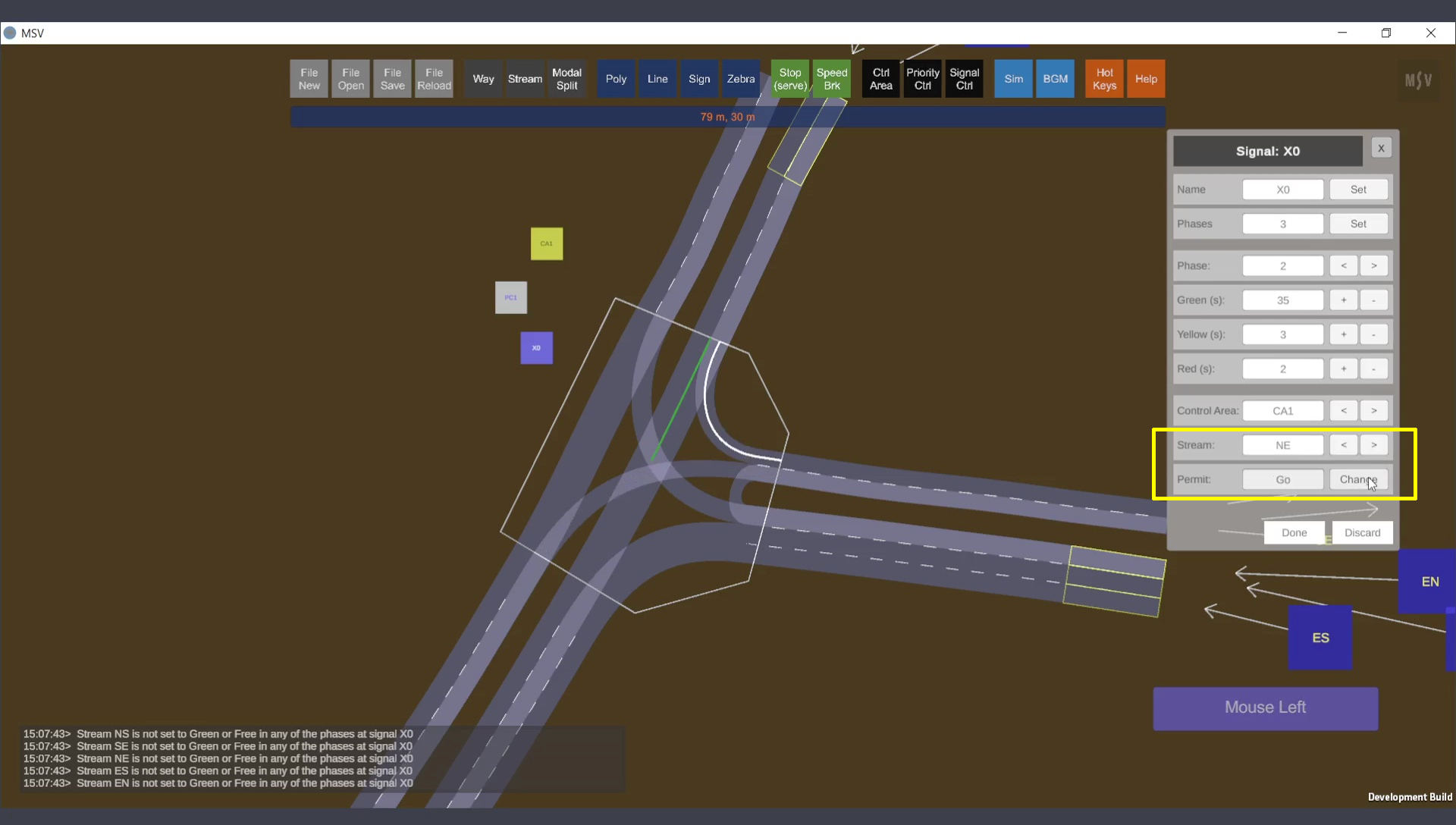
Phase 2: Streams starting from the north set to Go.
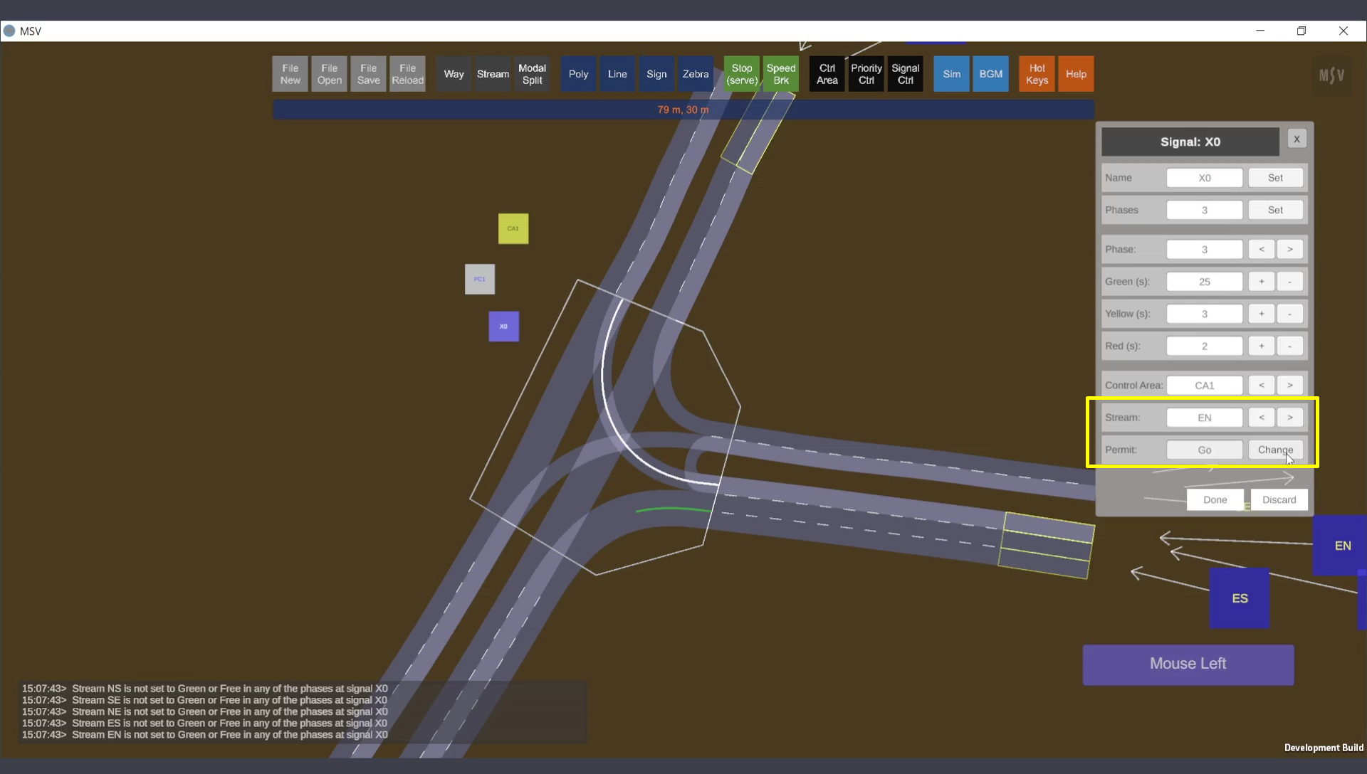
Phase 3: Streams starting from the east set to Go. U-turn (EE) intentionally left out (to see if the program warns about it).
Press Done, close the editor, save, and reload. The reporter window will display a message indicating that stream EE has not been assigned either a green duration or a free movement setting (as shown in the picture below).
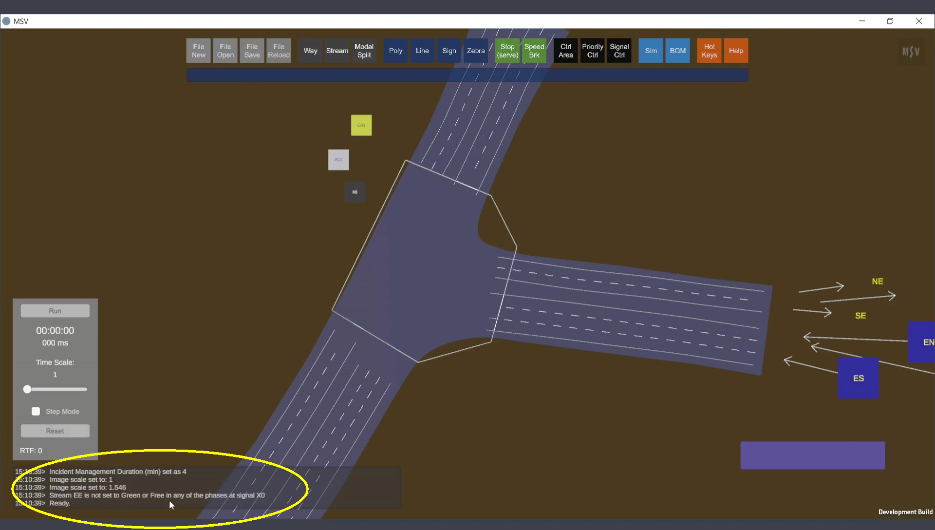
Reporter warns about a missed stream setting.
Set the U-turn stream (EE) to Go for phase 3:
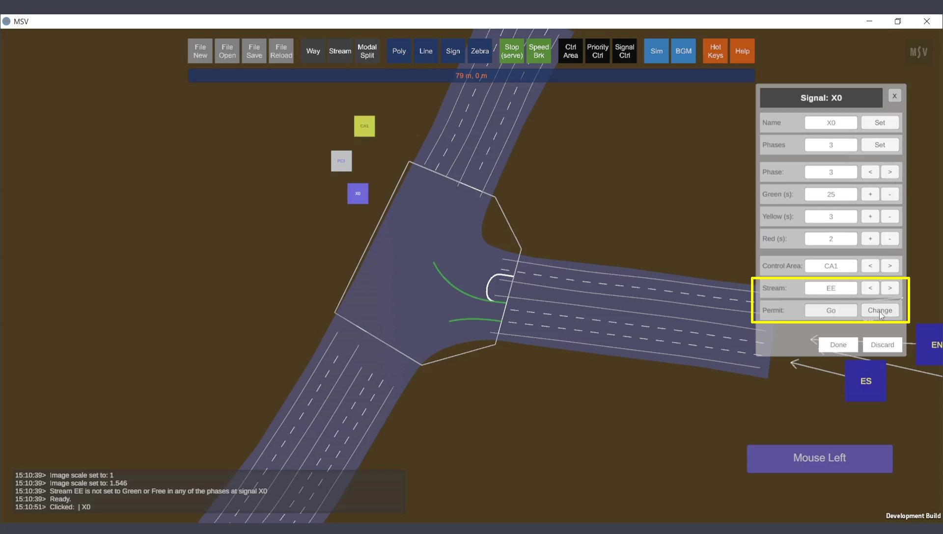
Phase 3 corrected for the U-turn stream.
The key difference between green and free settings is that, in the green setting, vehicles will clear the area during the yellow duration and stop during the all-red duration. In the free setting, vehicles will continue moving through all three stages within the phase—green, yellow, and all-red. The free setting is particularly useful for free-left movements in left-hand traffic conditions or free-right movements in right-hand traffic conditions.
Close the editor, save, reload, and run the simulation. The signal works, and direction lines for the active phase are displayed. Use the ‘X’ key to toggle visibility of these lines.
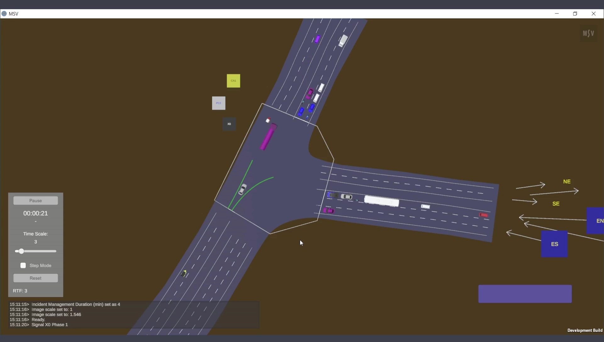
Signal working correctly with phase 1 running.