Procedure on how to add a background road layout image and then configure its scale is described here. Make sure the image has a scale clearly mentioned in the form of a line and its length. Or, any building or road portion should have a length marked. MSV uses meters as the unit. If the unit is in feet or inches, enter the value in meters where necessary.
Once the image file is available, place it in the BGM folder under the model folder. The file should be a PNG or JPG file. There should be only one file in the BGM folder to avoid confusion with other images to be used in the model, which are stored in the Signs folder.
Once a scale is set for the BGM, it should not be altered later. Alteration can be done before creating objects – which will be based on the scale. Altering the scale afterward must be avoided. Once a road is created using a scaled image, altering the image will cause distorted views for the road, which might appear smaller or larger than it should. Hence, it is better to take time to scale accurately and leave it as-is for the current model.
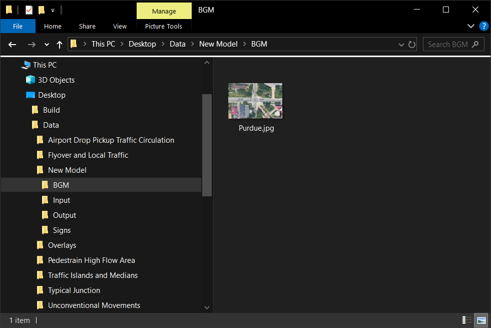
Keep one PNG or JPG image in the BGM folder as reference
Once the background image is in the BGM folder, open MSV and open the model folder. If the model is already open, just reload it so that the software recognizes the image file.
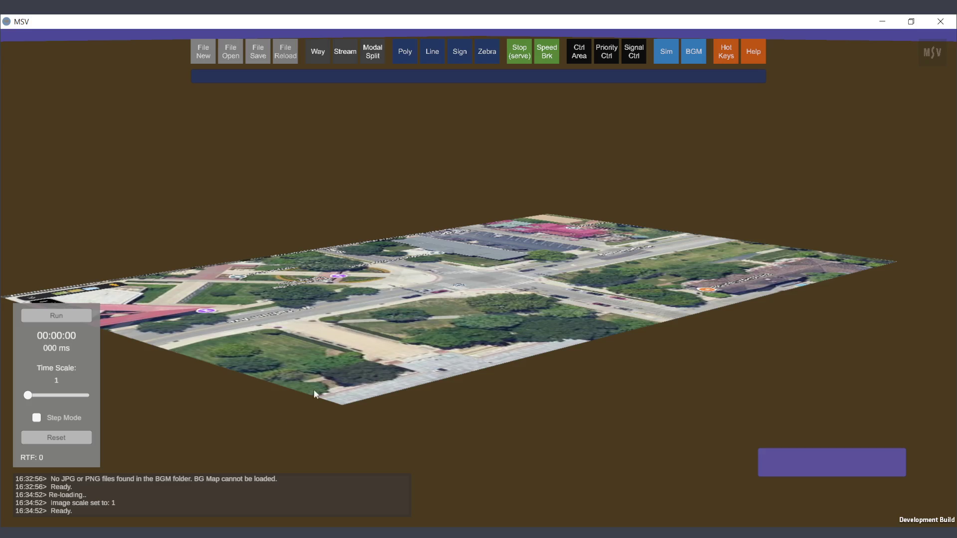
This is how the map looks when opened the first time
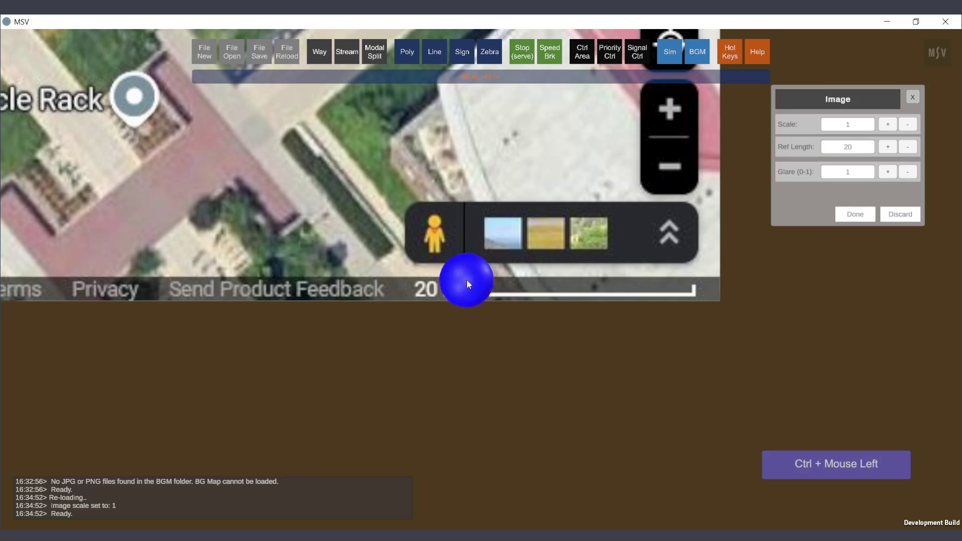
The next step is to set the scale for the image. Images can be of any size. Each pixel might represent some length in the 3D view. We want to ensure the scale in the 3D environment matches the scale in the image. Click the ‘BGM’ button in the top row of buttons to open the BGM Editor.
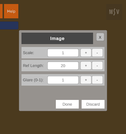
BGM Editor’s default view
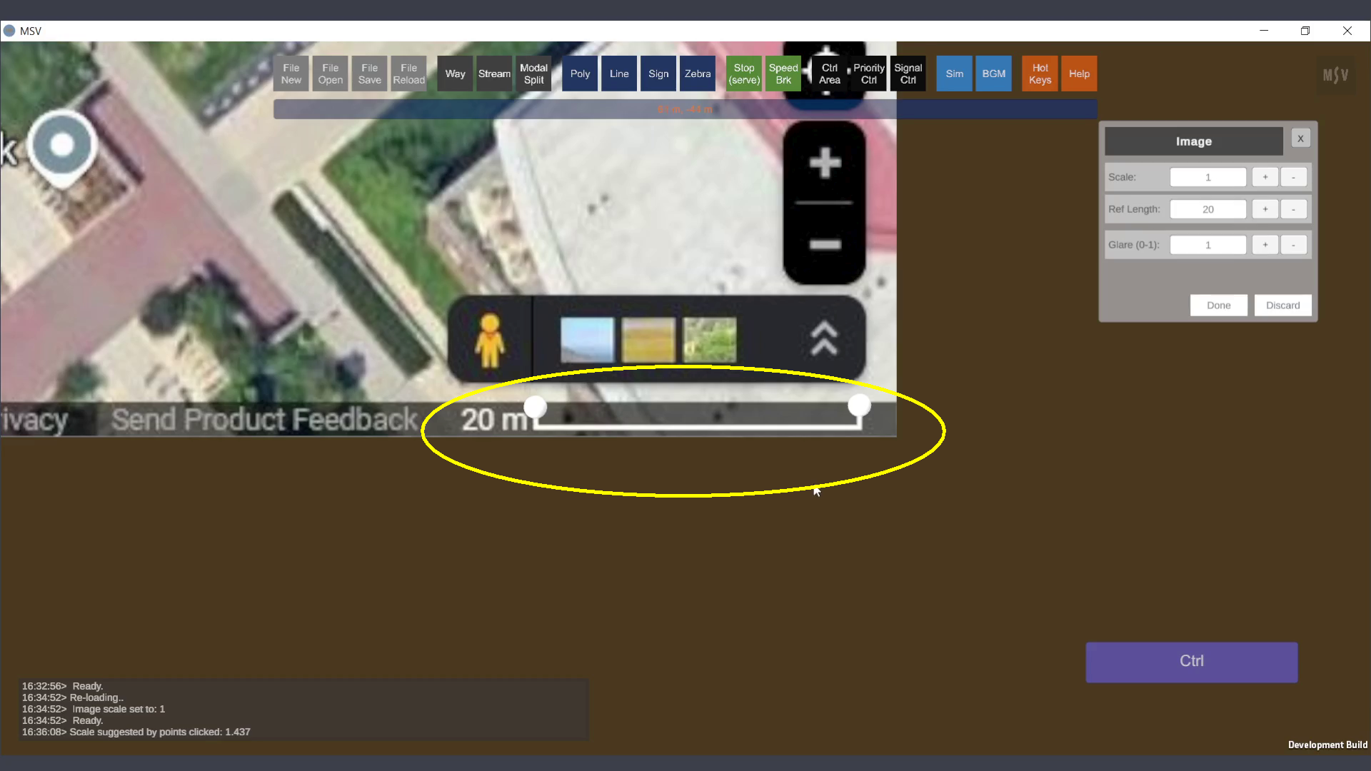
By default, the editor shows a scale of 1, a reference length of 20m, and a glare value of 1. The scale determines how much the image should be stretched to match the 3D environment's scale. The reference length is the real-world distance between two chosen points on the image. Glare adjusts the brightness of the image, as CAD images can sometimes be too bright, making other 3D objects less visible.
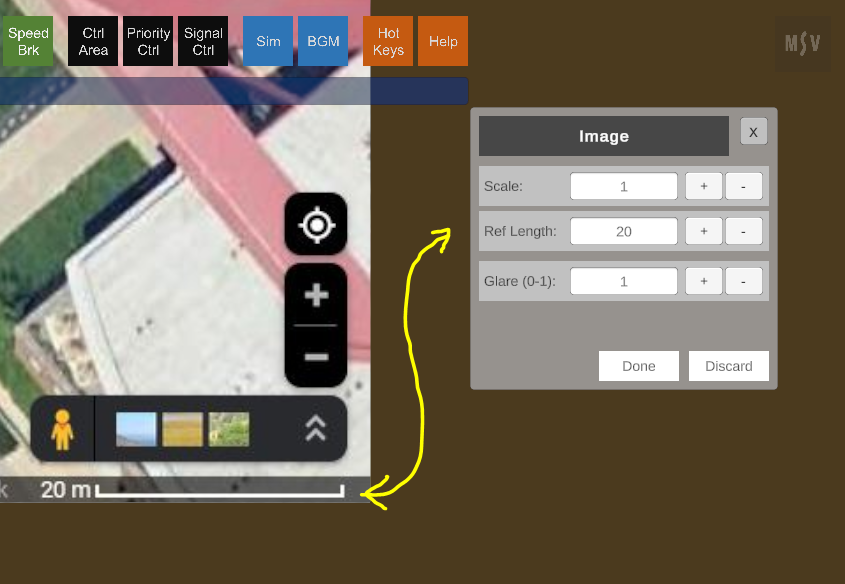
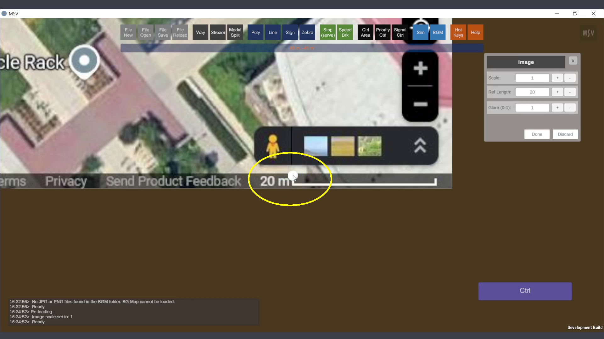
Satellite map showing a 20m scale, entered in the text field in the editor
For images with a different scale (e.g., 10m or 50m), enter the value in the Ref Length field and press Enter. For images without a scale marking, use known dimensions like building or road lengths marked on the image.
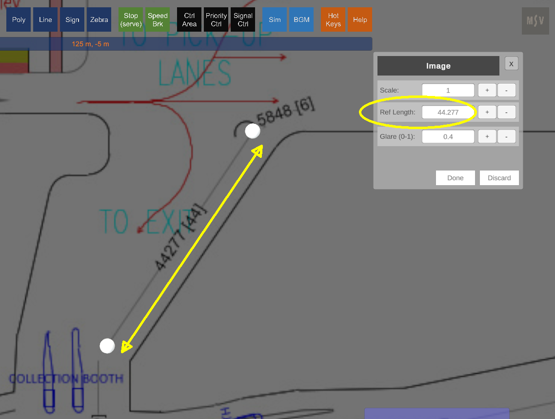
A length of 44277mm in the image is set as 44.277 reference length
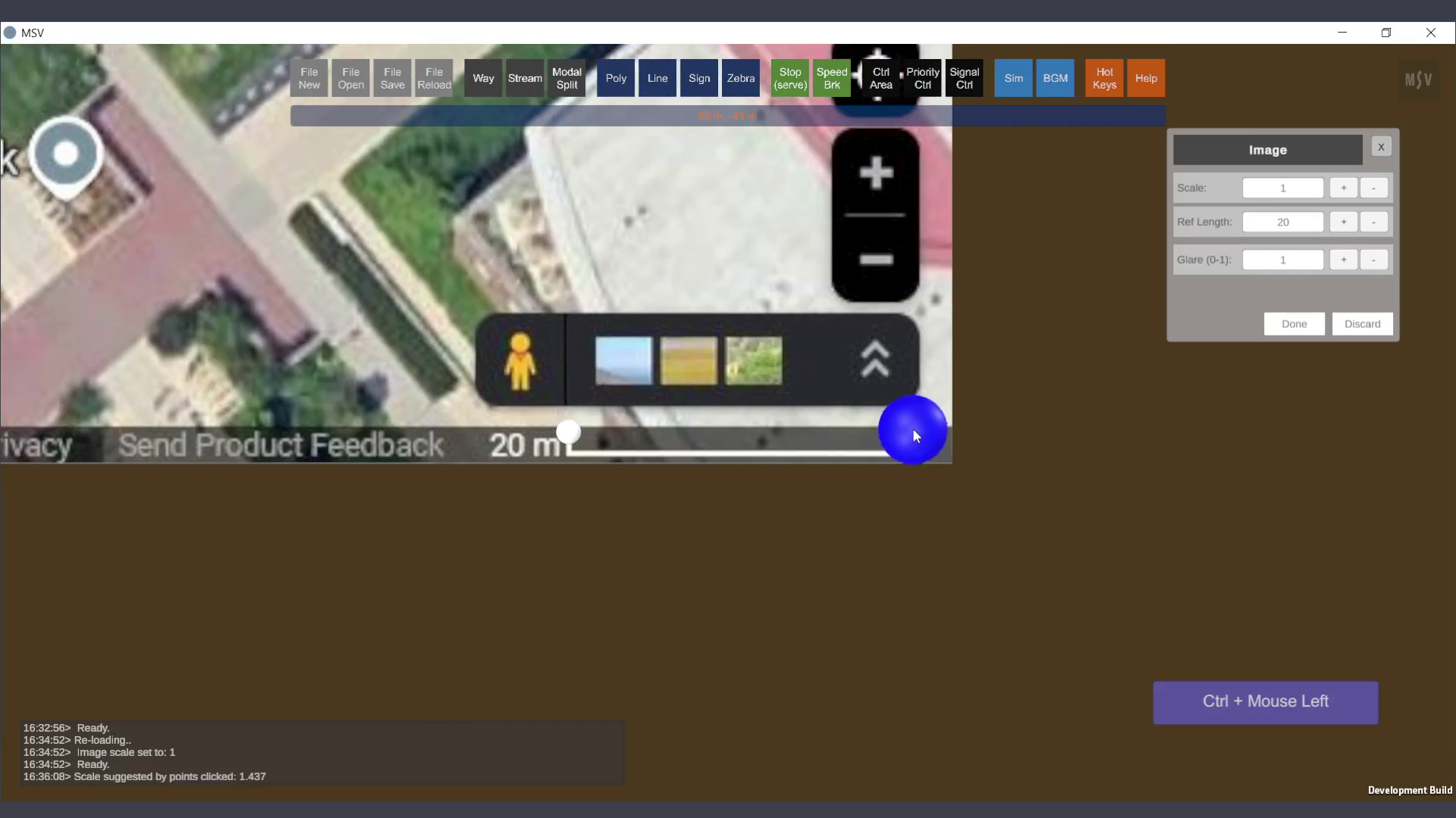
Use Ctrl + Left Mouse Click at two spots on the image to mark the ends of the reference line. MSV will animate the action with a blue blob that turns into a white blob.
The moment when Ctrl-Click was done on the left end of the scale line
Immediately it turns into a white blob denoting where we clicked
Second spot clicked (pressing Ctrl key) on the other end of the line
Two blobs indicating the program the two spots on the image
After placing the blobs, enter the reference length in the text field. The program calculates and displays the scale in the Reporter. Enter this scale value in the Scale field and press Enter. The image size will adjust accordingly.
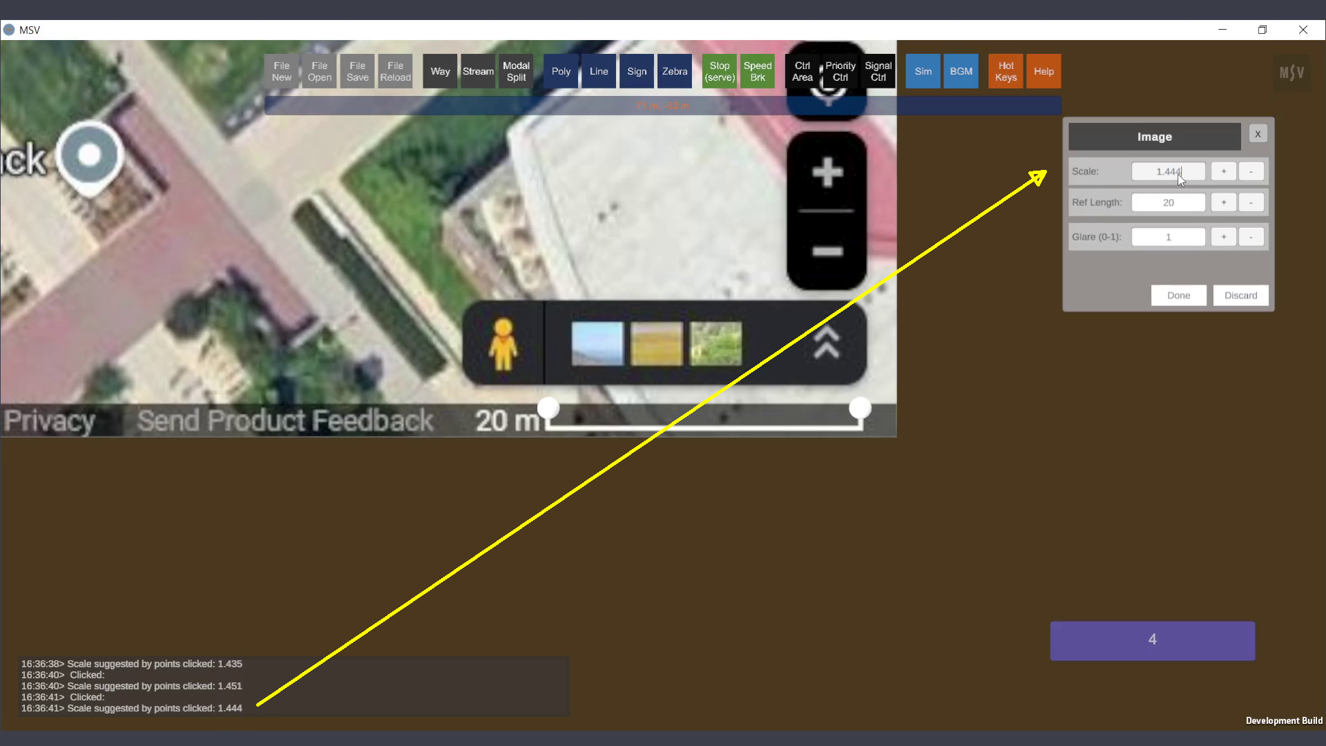
Entering the scale read in the reporter
Press the Done button, close the Editor, save the model, and reload it. The image will now be scaled correctly and ready for further operations.
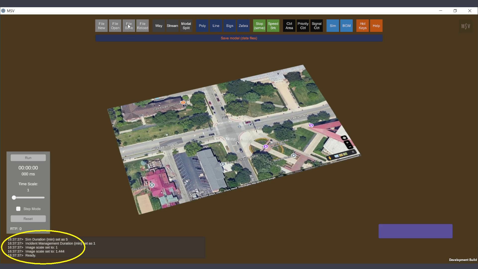
After saving and reloading, the reporter updates with the new scale
In summary, select two points on the image with a known distance, enter this distance in the Ref Length field, read the calculated scale in the Reporter, and input it into the Scale field before pressing Done.