In MSV, a control area is used to resolve conflicts between vehicular movements. When two or more streams cross each other, conflict possibilities arise. A well-known example of this is a junction (or intersection). A control area is the opposite of an uncontrolled intersection, where vehicles from various streams rely on mutual cooperation to avoid collisions. Uncontrolled intersections are acceptable when the flow is not high enough to cause significant conflicts or collisions.
To create a control area, an area is demarcated where streams intersect. The control area is represented as a multi-segment line cutting through the streams that need control. The program automatically includes streams based on their alignment with the control area’s perimeter line. Users only need to draw the line defining the control area. The shape includes a handle quad in the form of a yellow box displaying the control area’s name.
Below are examples of control areas in MSV:
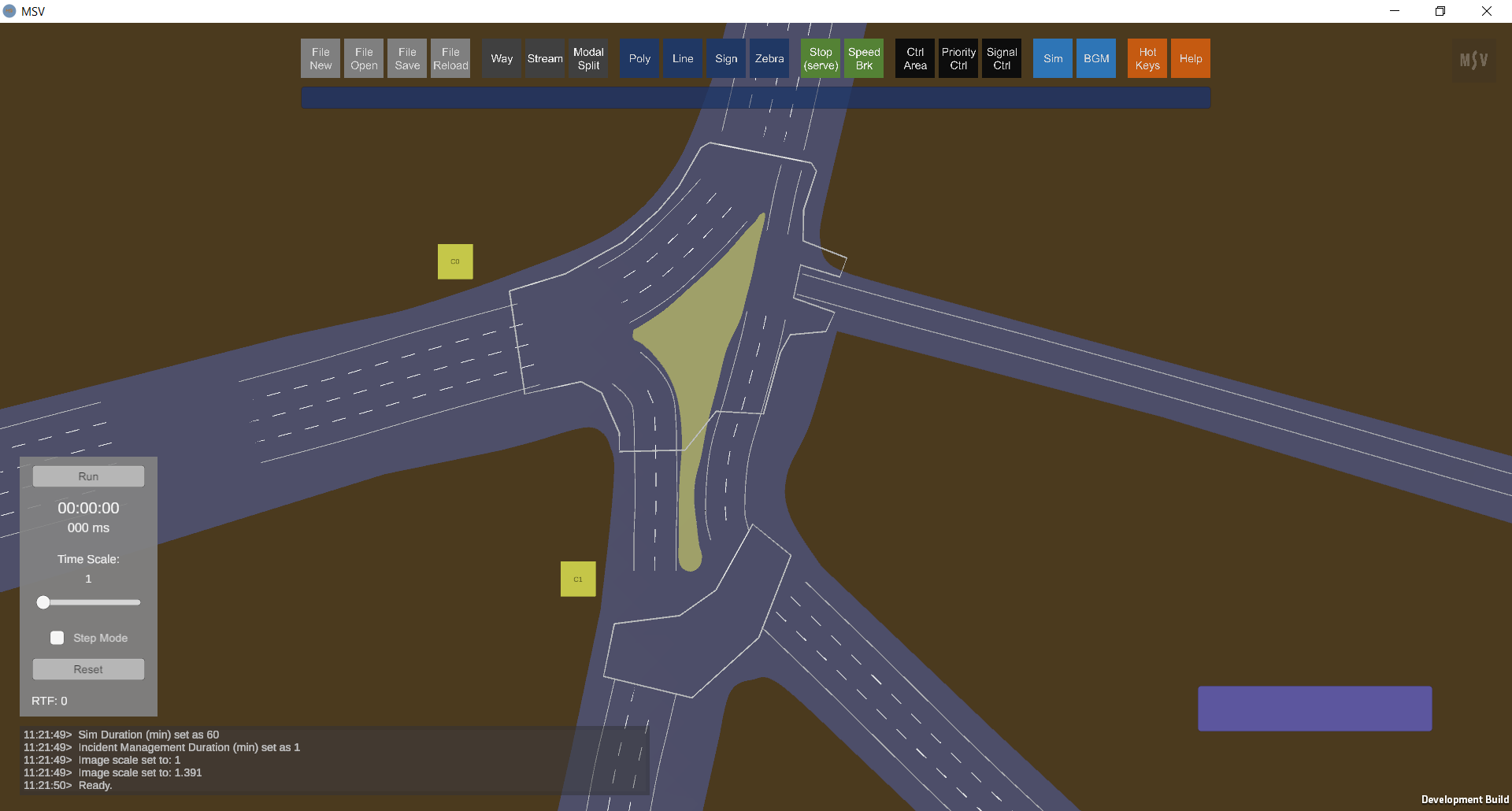
There are two control areas in this junction. Streams are switched Off, while Ways and Polys are On.
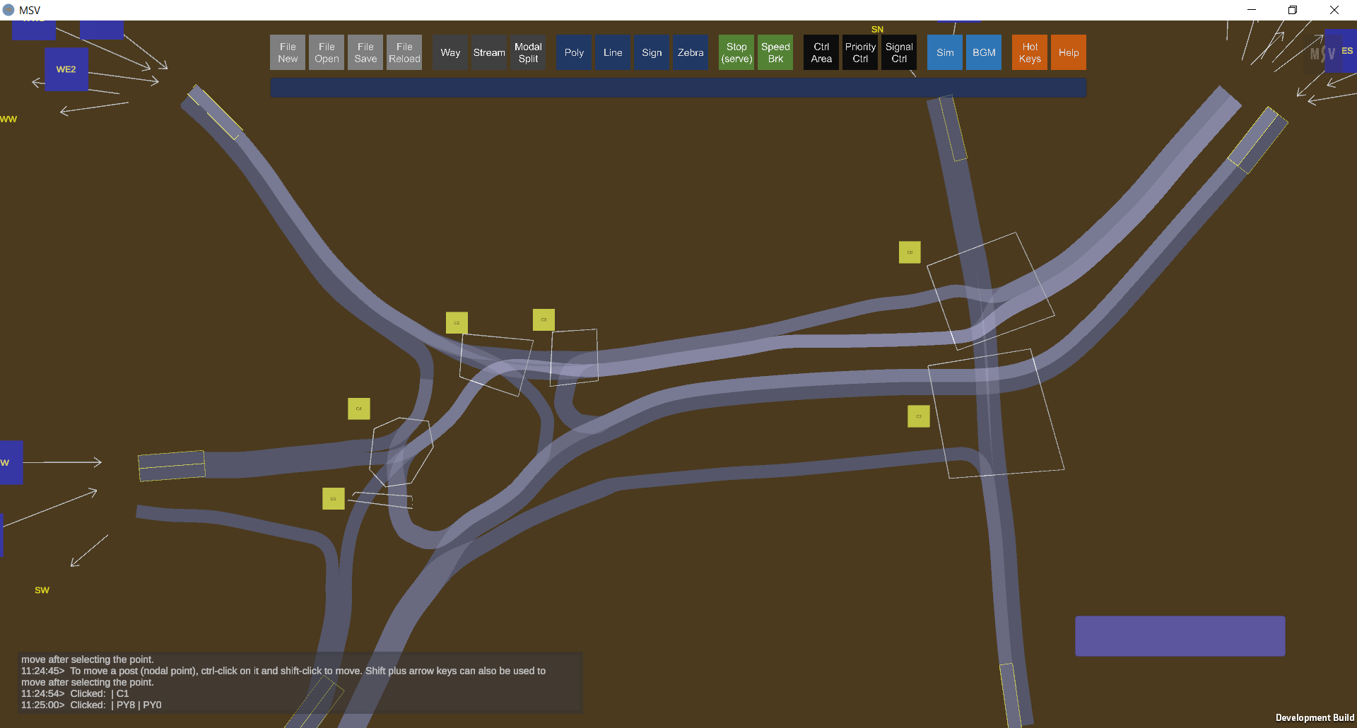
There are six control areas in this model. Ways and Polys are hidden, while streams are switched On.
In the following screenshot, note that the control area covers all possible conflicts, even though conflicts may occur only in the middle of the junction:
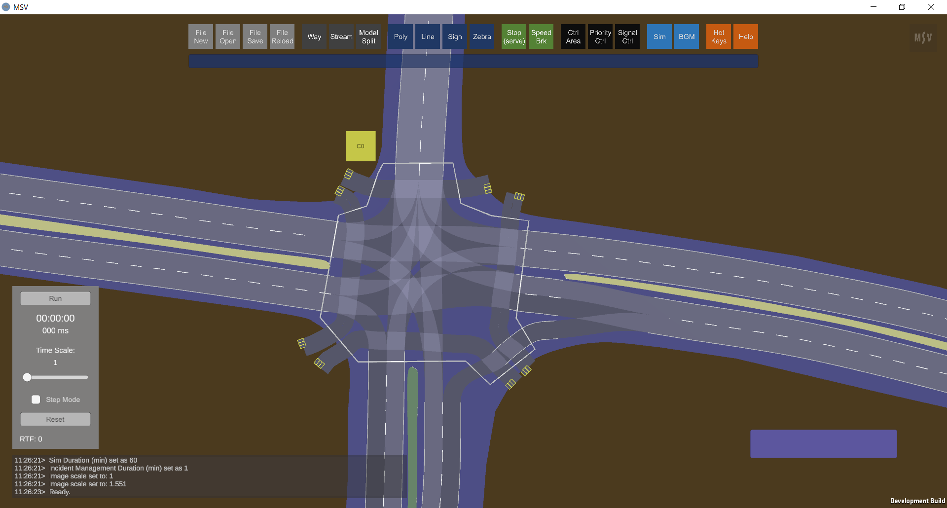
This control area manages 12 vehicle streams and 8 pedestrian streams.
Consider the following T-junction in Mysore, India:
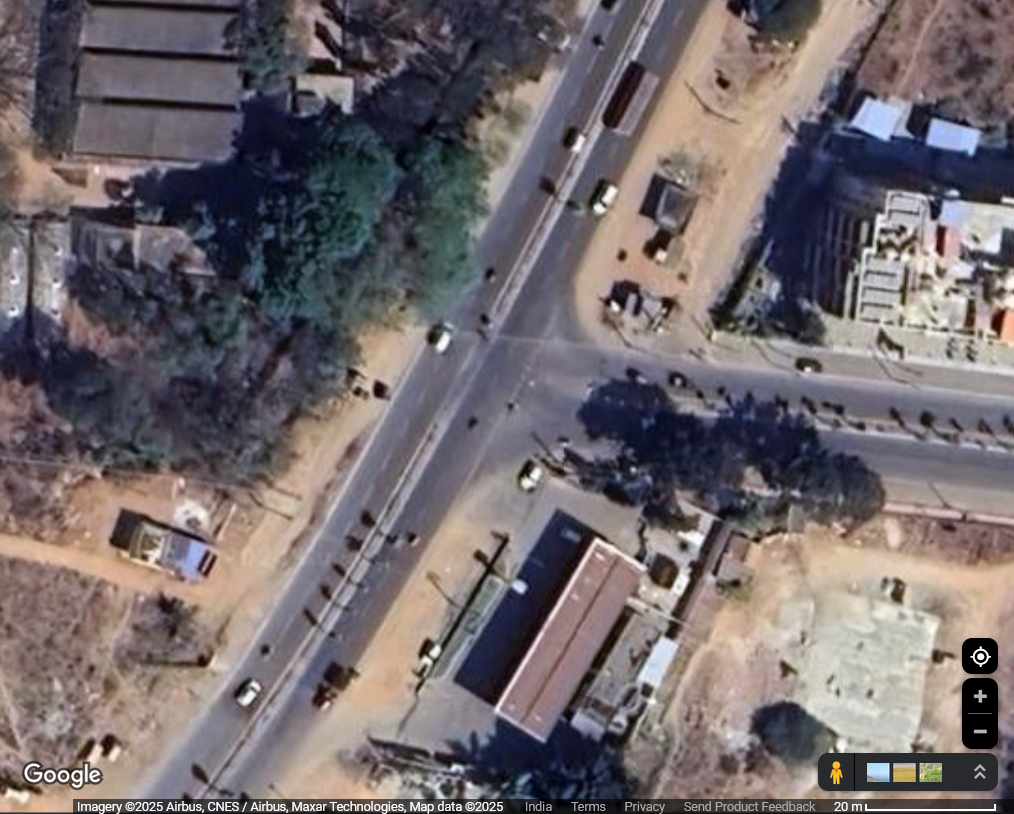
Junction modeled to describe the creation of a control area.
The modeled T-junction in MSV, with ways and streams set up, looks as follows. Vehicles move uncontrolled for now:
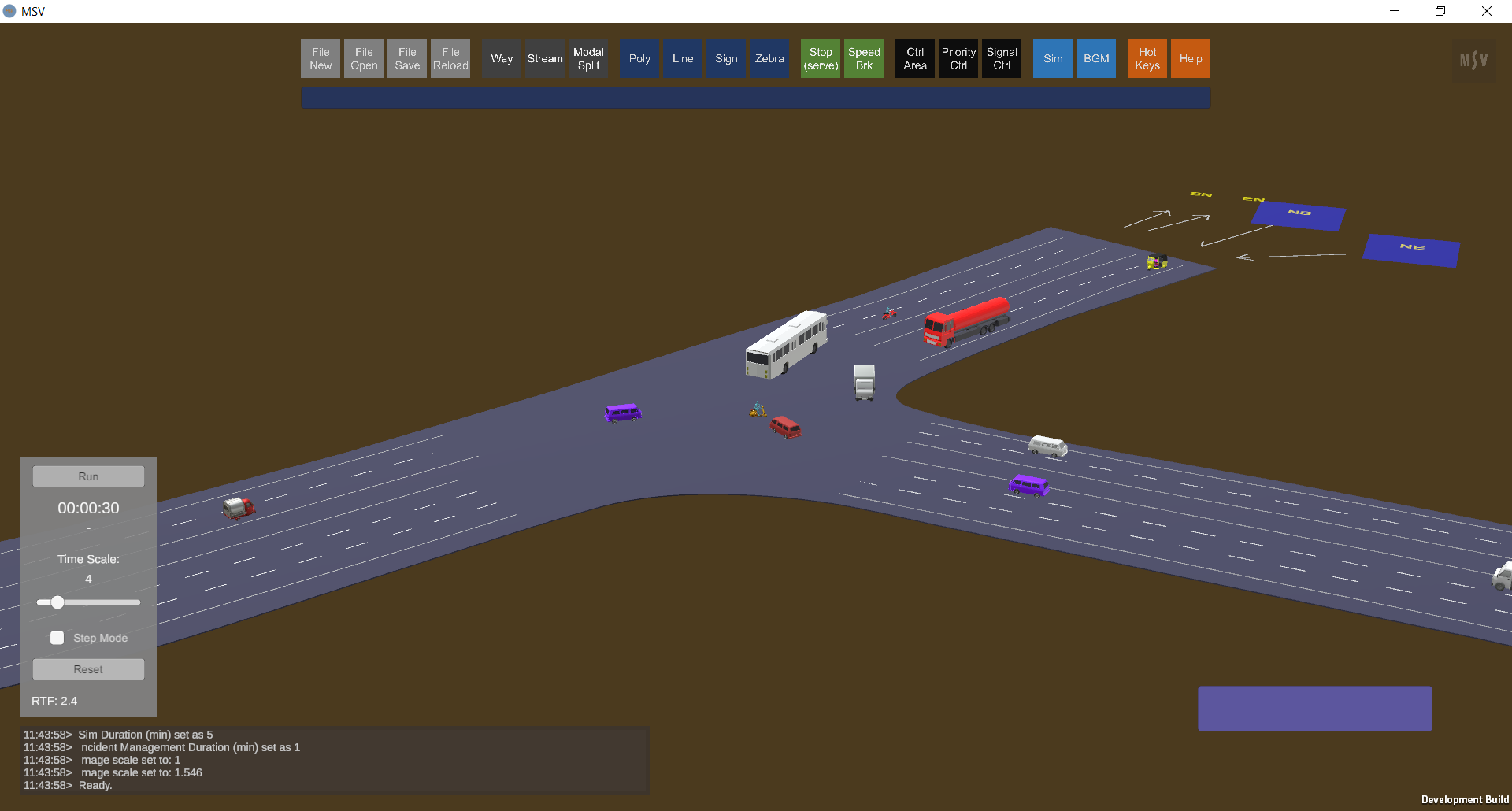
The junction as modeled in MSV, with control mechanisms yet to be specified.
To set up a control area, identify where streams intersect. Switch off the visibility of all other objects and switch on streams only, as shown below. Streams are labeled using directional notations (e.g., SN for South-North). Note that overlapping streams moving in the same direction are not considered conflicting streams. This requires visual verification in the field and through simulation to decide whether to add a control method or observe the effect of no control.
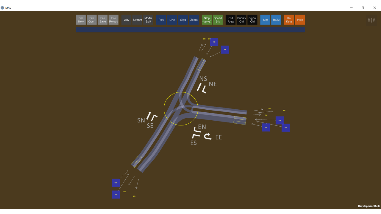
Seven streams to be controlled by one control area.
To specify a control area, click on the ‘Ctrl Area’ button. The editor includes three input fields:
Defining a control area begins with a Ctrl-Click near the junction. The first click creates a yellow box (handle quad) displaying the name. Subsequent Ctrl-Clicks form the connected line for the control area.
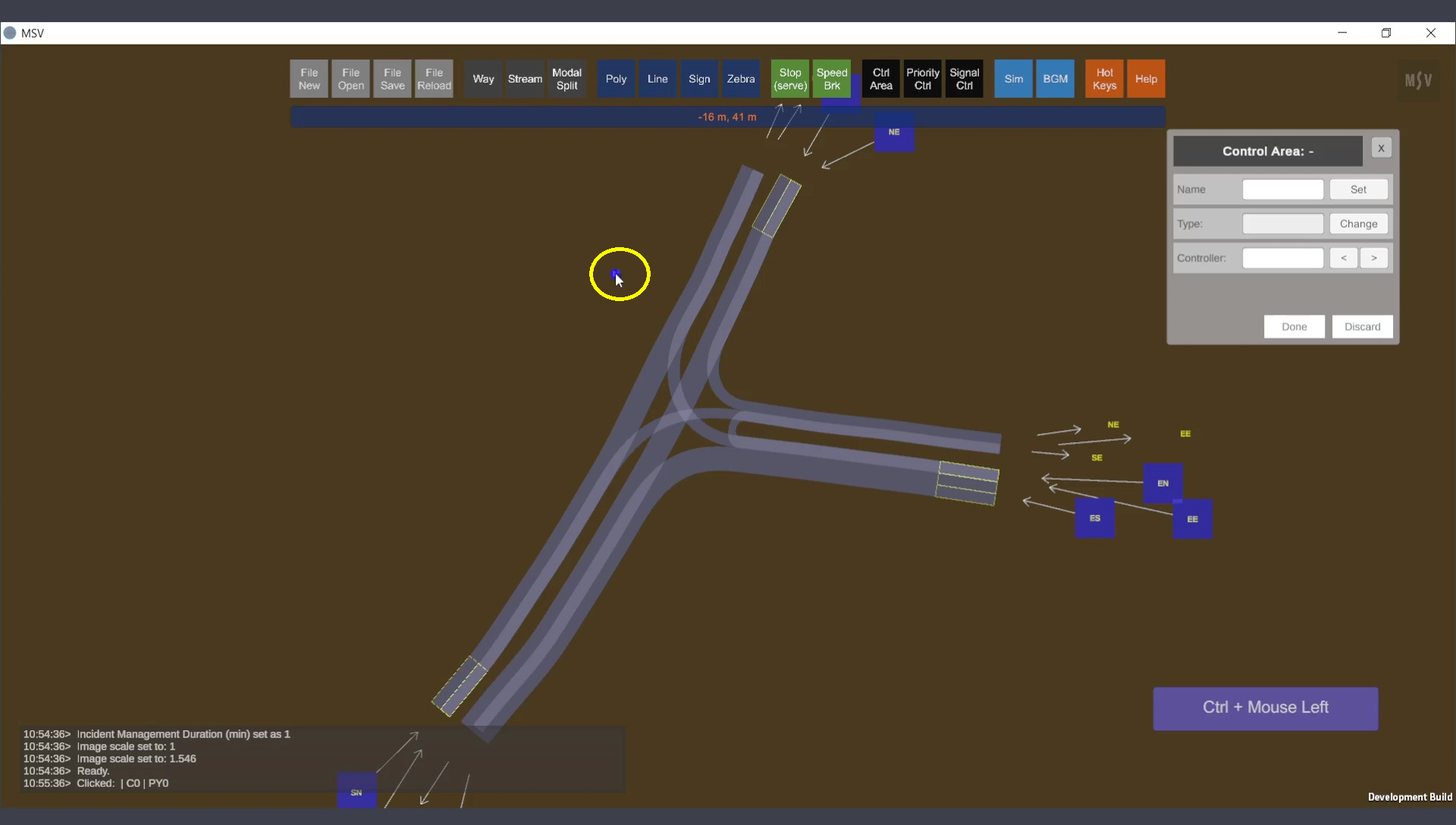
First Ctrl-Click creates the name quad near the control area.
Continue Ctrl-Clicks clockwise, covering the streams on each side of the junction:
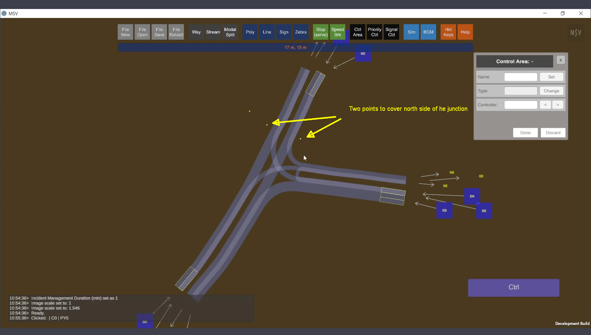
North side of the junction is covered.
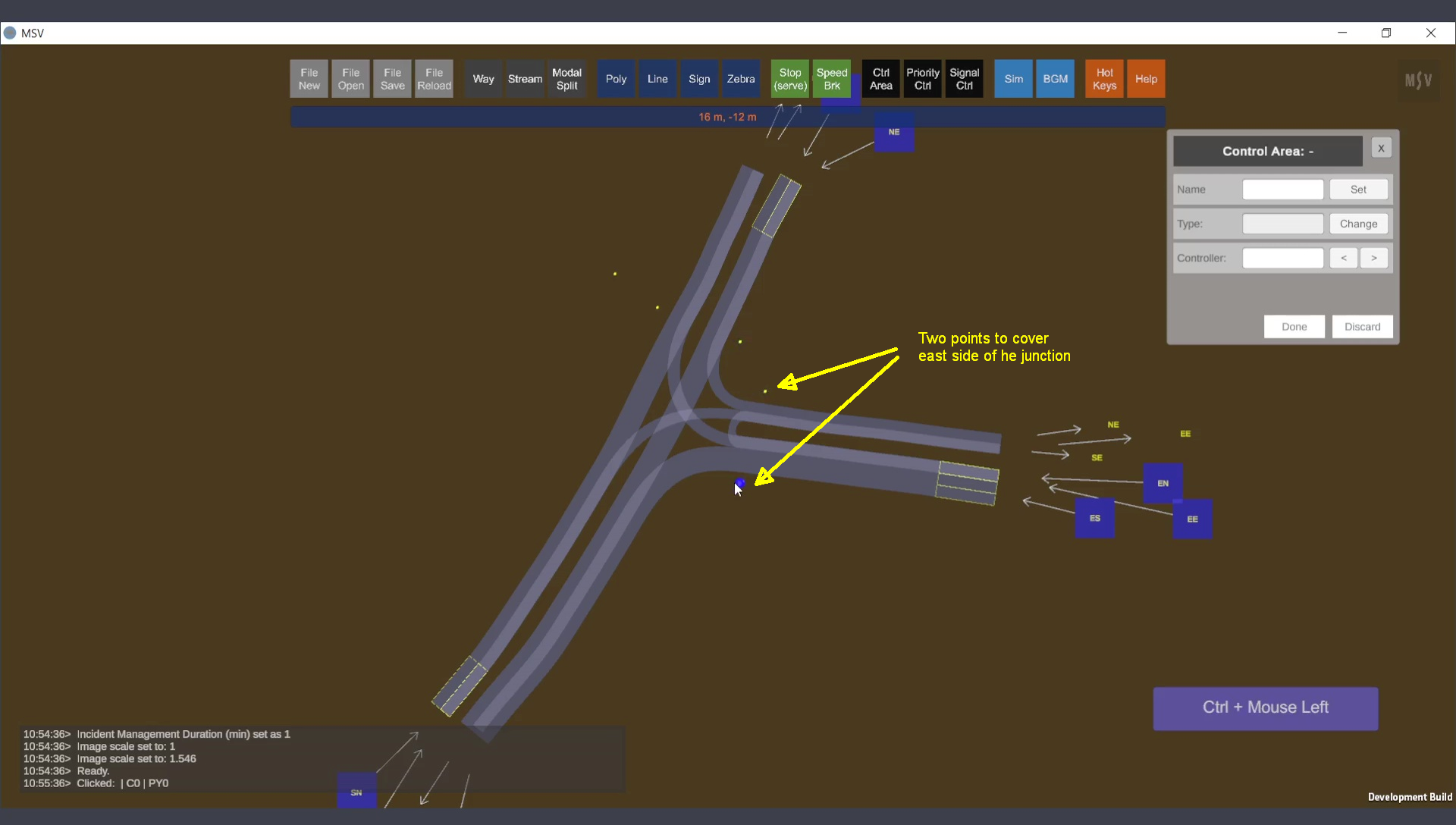
East side of the junction is covered.
Finally, complete the control area by covering the streams on the south side. If the approach roads have a stop line marked in the real world, ensure that the control area extends over them, as vehicles stop at the line where the control area intersects the stream. This will accurately model where vehicles stop in reality. Press the Done button to automatically connect the last point to the first (excluding the point reserved for the handle quad):
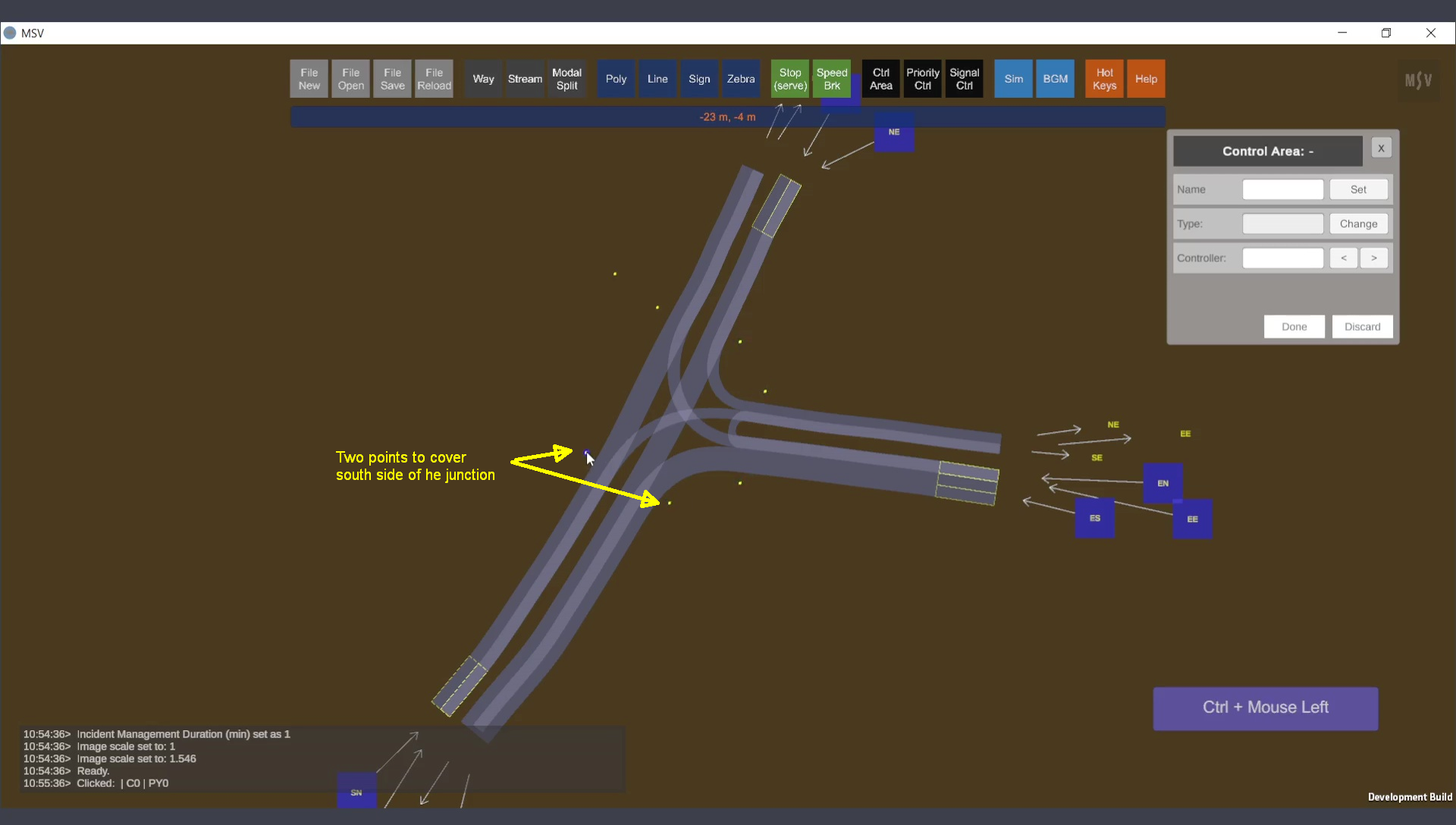
South side covered. Ctrl-Clicks are completed.
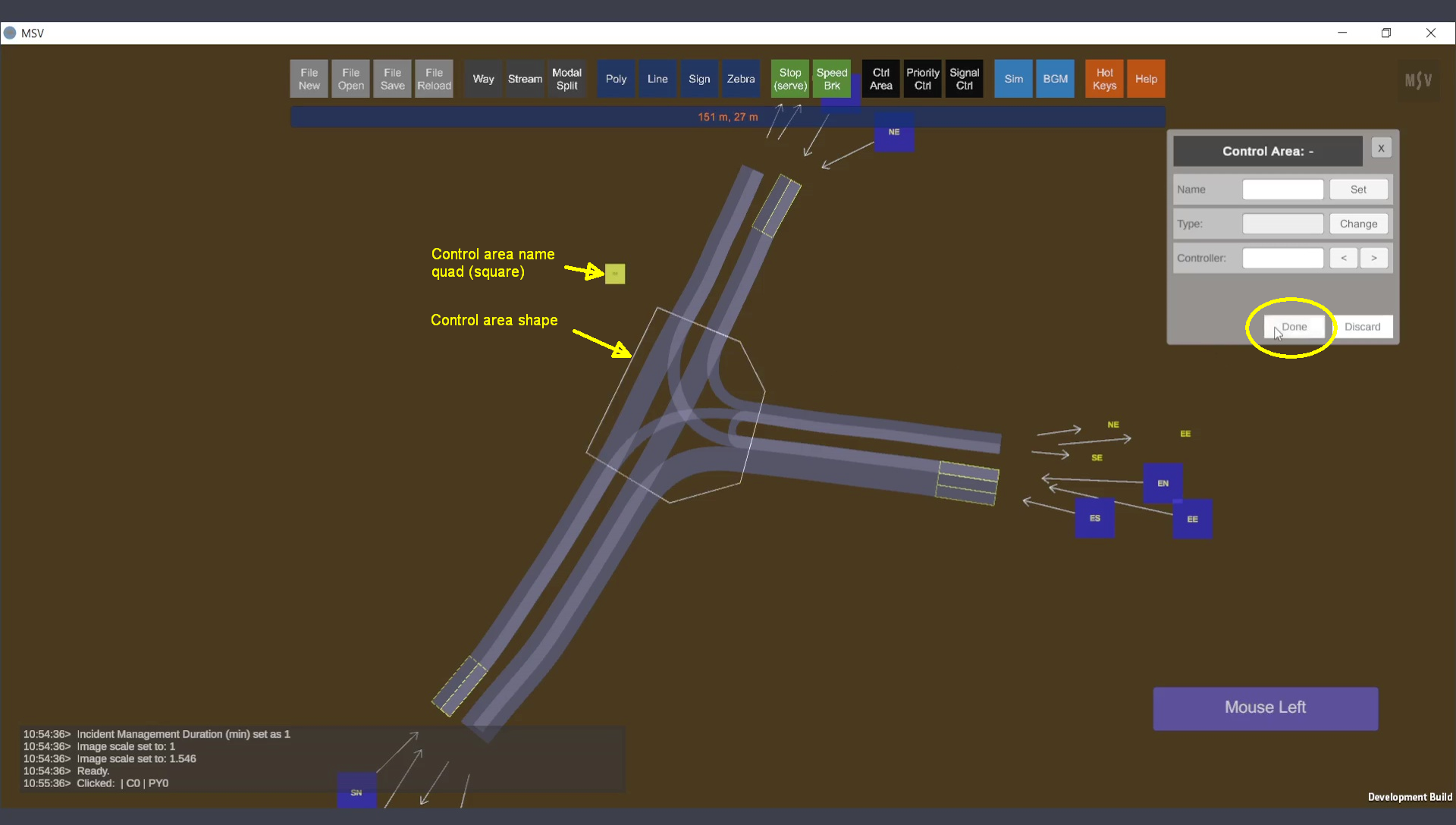
The completed control area with a name quad and a line cutting through all streams.
Individual control points can be adjusted, removed, or inserted as needed:

Control area can be reshaped as required (e.g., when way objects are reshaped).
When configured correctly, a control area intersects each stream twice (e.g., the SN stream enters and exits the control area). The program recognizes these as entry and exit points. If the configuration is incorrect, the reporter will provide messages, prompting the user to reshape the area.
The visibility of control areas can be toggled using the letter ‘C’:
These hold lines dictate where vehicles stop (signal control) or yield/stop (priority control). Further details are covered in the priority control and signal control sections of the manual.