For road markings such as arrow marks, yield signs, etc., it is often useful to use images rather than asking the program to draw such shapes. This approach allows locally approved signs to be displayed in the scene. For example, consider a left-arrow mark. Its size and shape can vary from location to location or country to country. While the differences may be subtle, using signs practiced in the study area enhances the model's visual accuracy.
Images for basic arrow types such as left, straight, right, U-turn, and their combinations are provided with the installation files. These images are stored in the common Signs folder. They can be copied to the Signs folder created by the program under the model folder.
The image below shows two Signs folders: one outside the Data folder (provided with the program) and another under the New Model folder, where the files need to be copied. The blue arrow indicates where to copy and paste the files. The source and data folder locations may vary depending on the program's installation path and data model location.
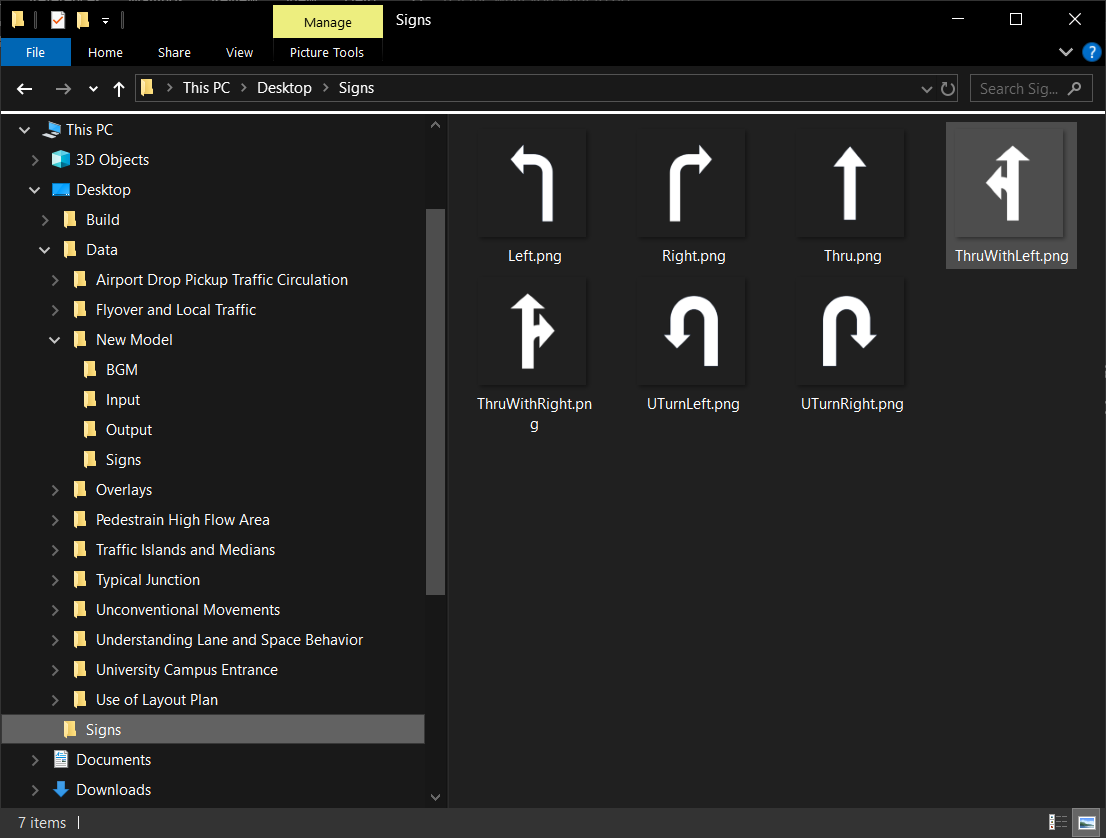
Basic images provided with the program. Copy them to your data folder’s Signs folder.
The procedure for adding a couple of signs, adjusting their position, and scaling them is described below:
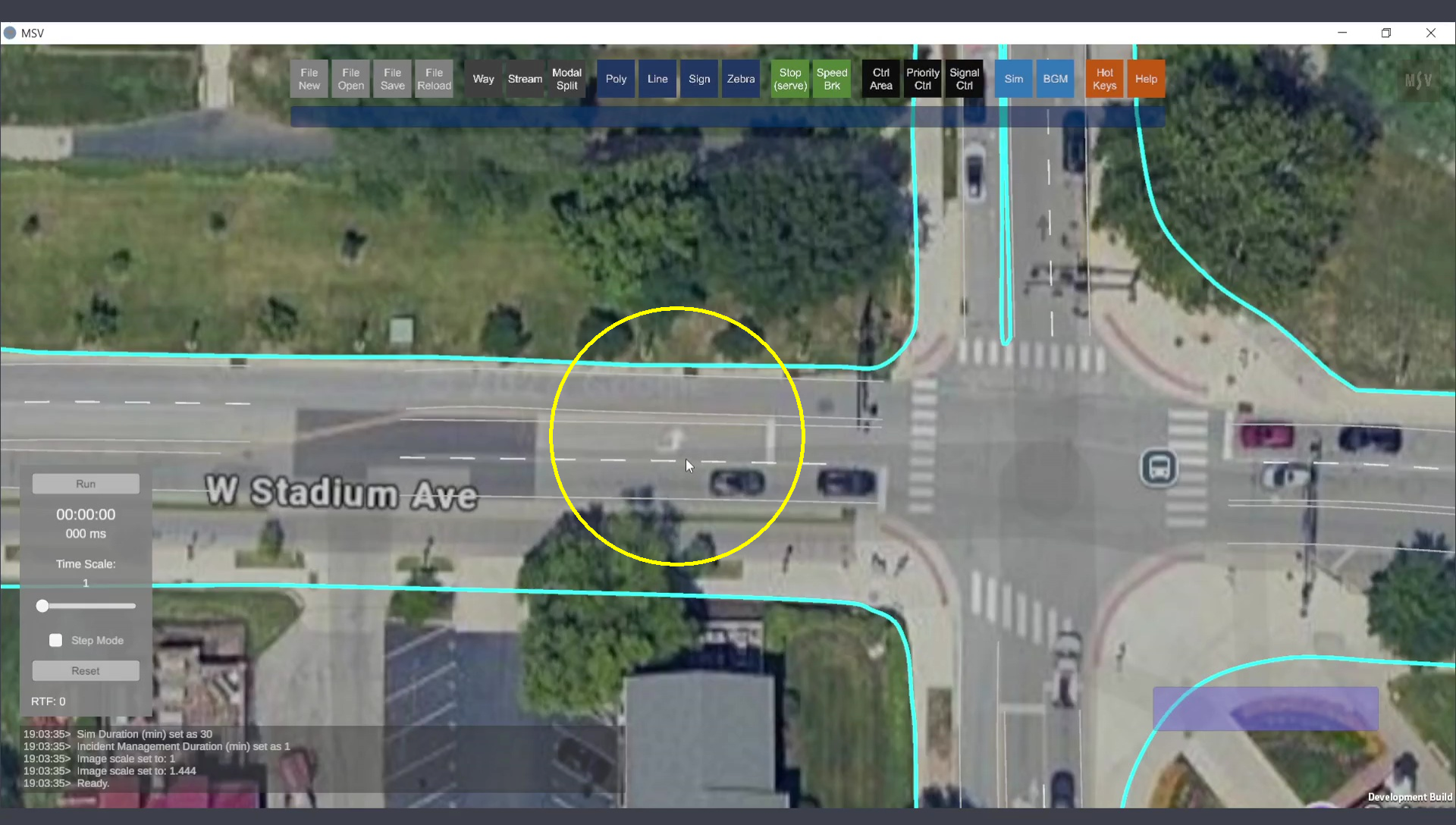
An arrow mark on the map where a sign will be created.
Open the Signs Editor by pressing the ‘Sign’ button. The editor includes the following fields:
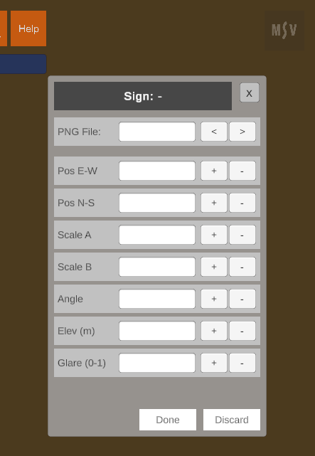
Signs Editor interface.
Unlike line shapes or poly objects, a sign requires only one control point: the location of the sign. A single Ctrl-Click followed by pressing the Done button is sufficient to create a peg (or post) at the location. The peg can be hidden once the image is placed.
When creating a sign for the first time, if no images are present in the Signs folder, a reminder message will appear:
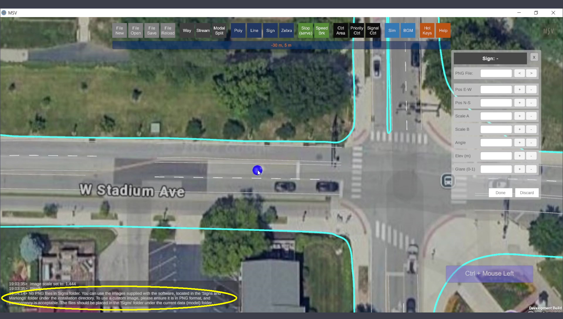
Message prompting to add images to the Signs folder.
Ensure the required images are added to the Signs folder, reload the model, and reopen the editor. Create a spot using Ctrl-Click, and press Done. The program will acknowledge the spot and allow you to select an image from the PNG file field. If no image is assigned, the field will display a “-” symbol.
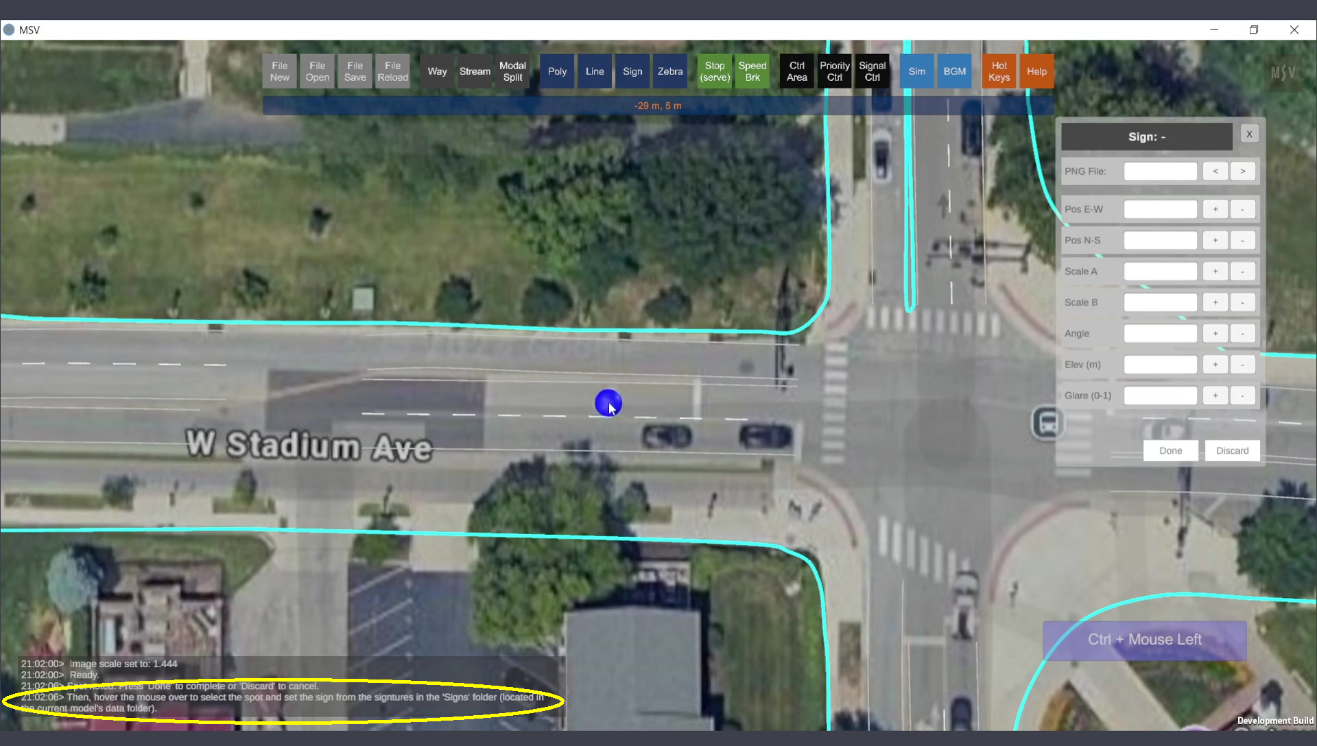
Message asking to select the spot and assign an image.
The "left arrow" image was chosen and appears at the selected spot with its default scale and orientation. Adjustments can now be made to the scale, angle, and position:
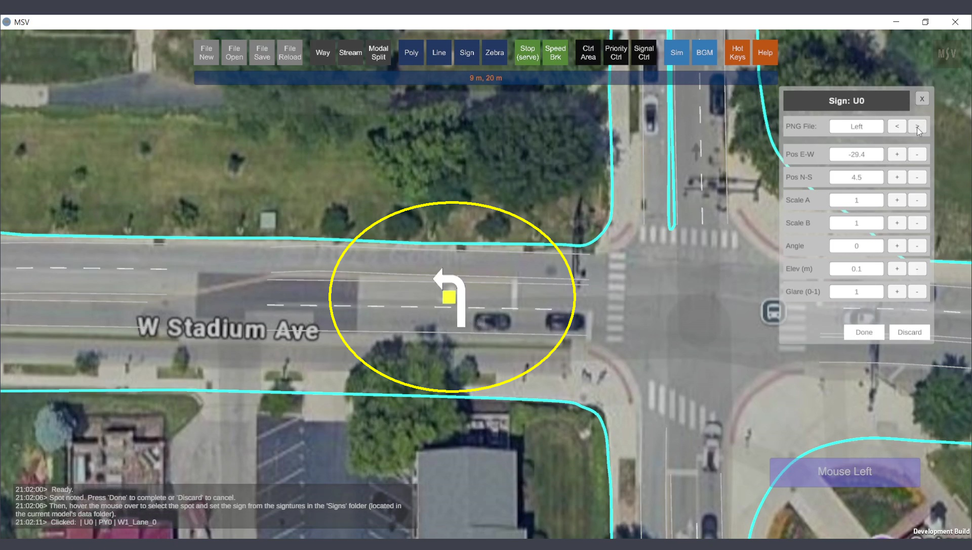
Initial placement of the left arrow image.
Adjust the values through trial and error until the sign fits perfectly.
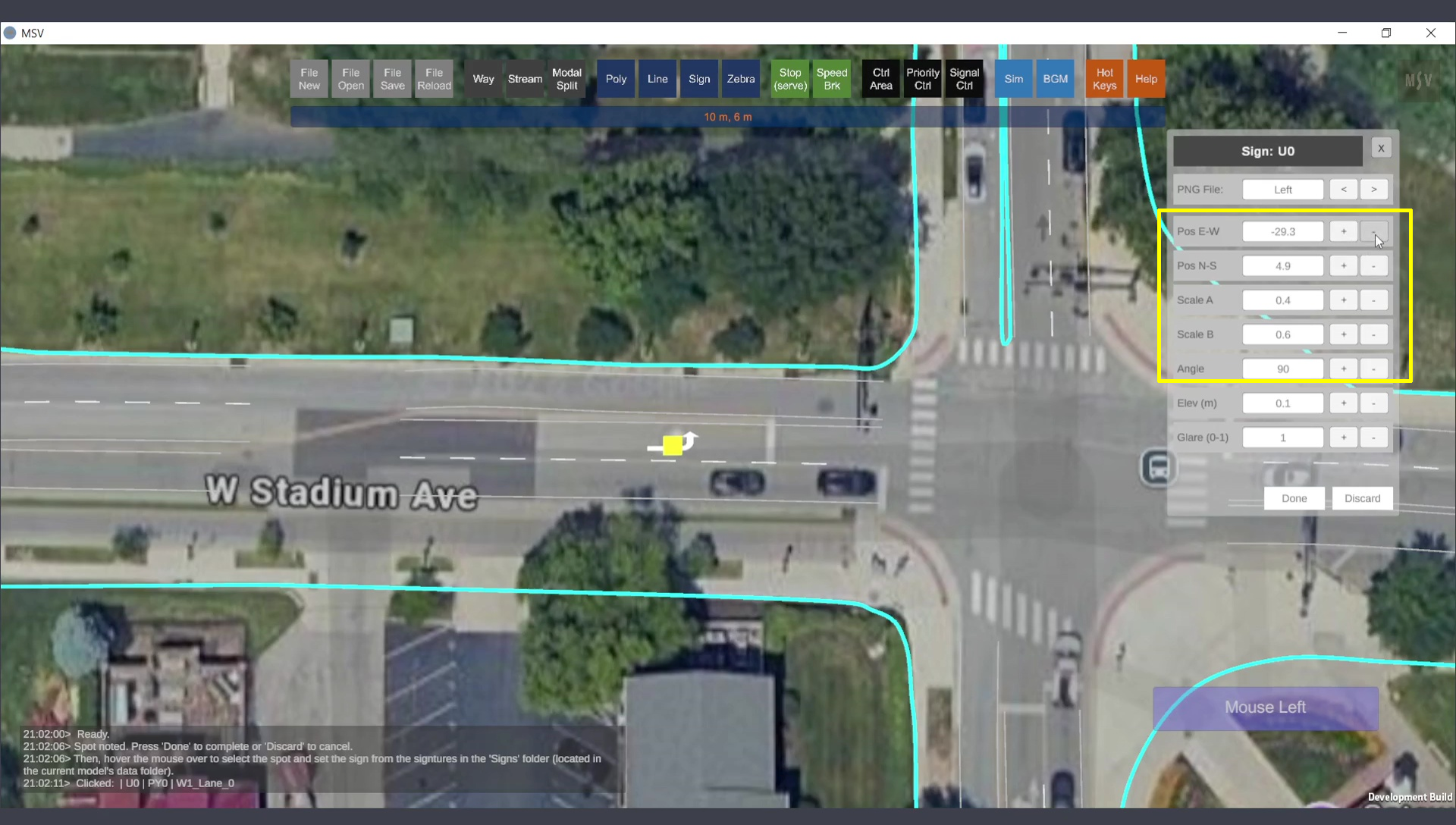
Adjusting scale, position, and orientation of the sign.
Once satisfied, press the Done button. The completed arrow sign appears as shown:

The arrow mark sign added to the map.
Next, a second sign is added to the map using the "ThruWithLeft" image:
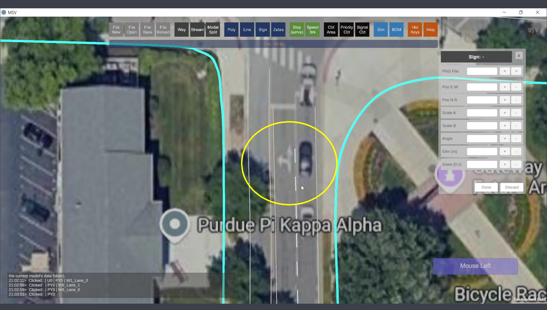
Spot for the second sign.
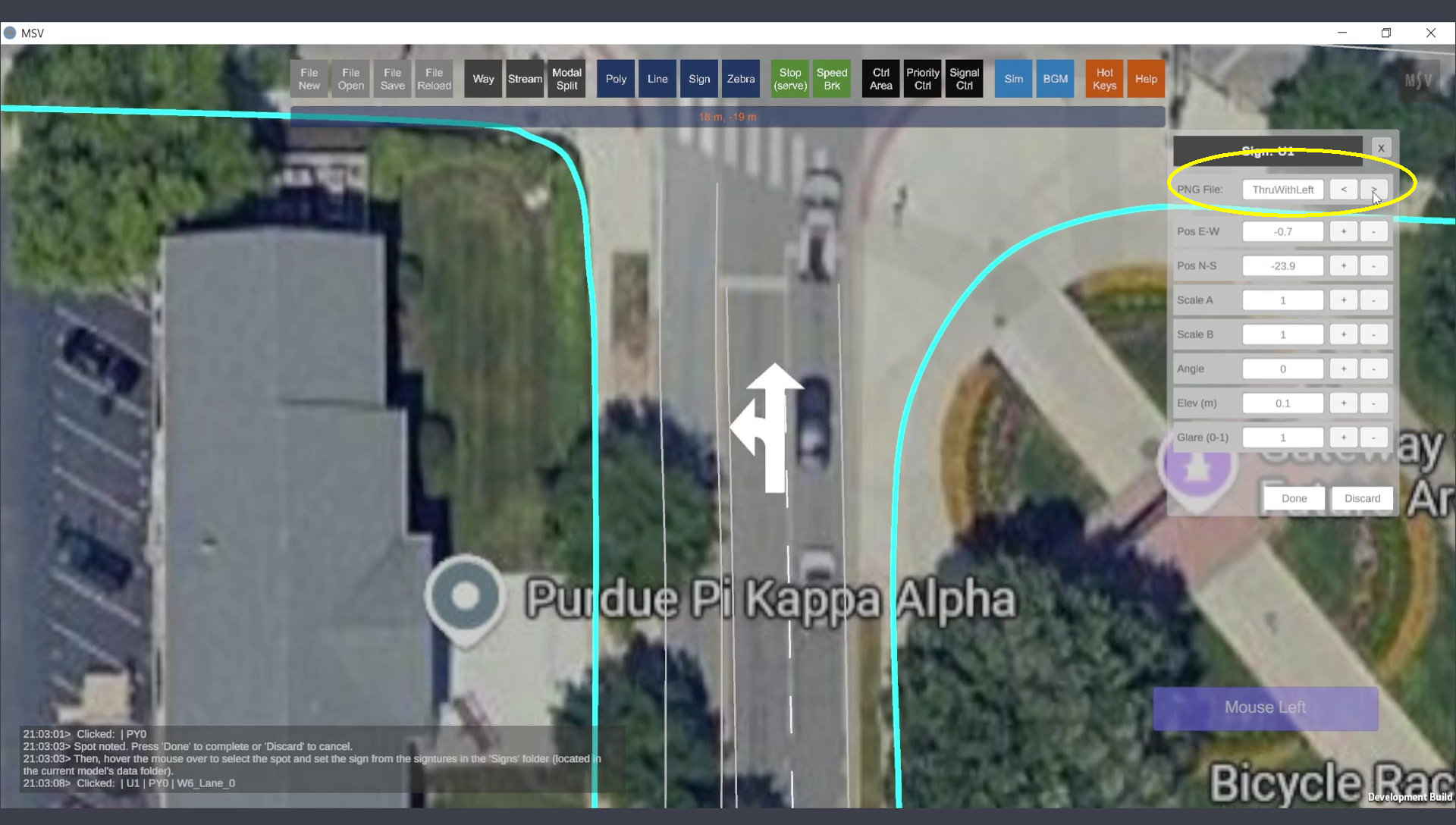
Default placement of the second sign.
After adjustments to its position, scale, and angle, the final appearance is shown below:
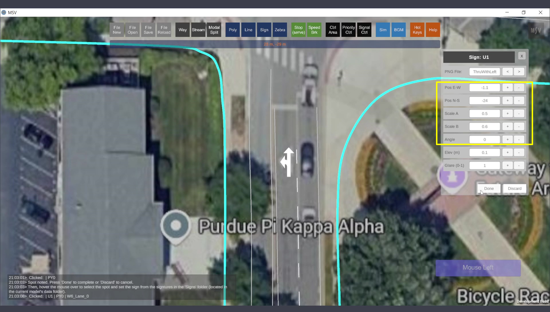
Final look of the second sign after adjustments.
Both signs are displayed as follows when the background image is hidden and the poly base is switched on:
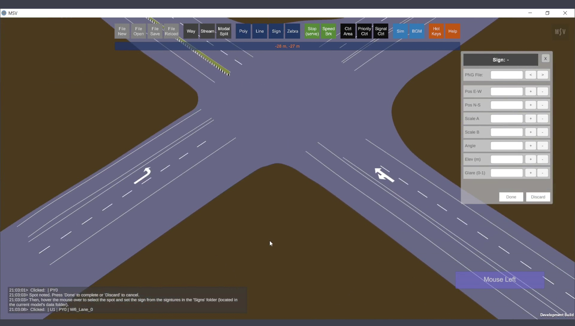
Both signs added to the model (for right-side traffic).
Annotations such as street names, model names, or special notes can also be added as images. Creating text images is simple using online font generators or programs like Microsoft Word or PowerPoint. PowerPoint slides can be exported as images, and tools like GIMP or online platforms can be used to remove backgrounds and create transparency where needed.
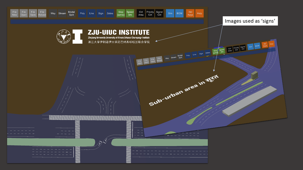
Using images for annotations eliminates language barriers in presentations.
Additional maps can also be imported via the Signs Editor. Ensure proper scaling for these maps. Images can be stacked vertically for multi-level modeling, such as different building floors or vehicular movements. An example is shown below:
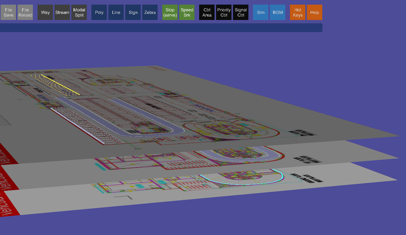
The Signs feature can also be used for importing and placing additional images.
In MSV, signs are versatile tools for adding road signs, markings, images, or additional maps. They aid in modeling and enhance presentation aesthetics.